
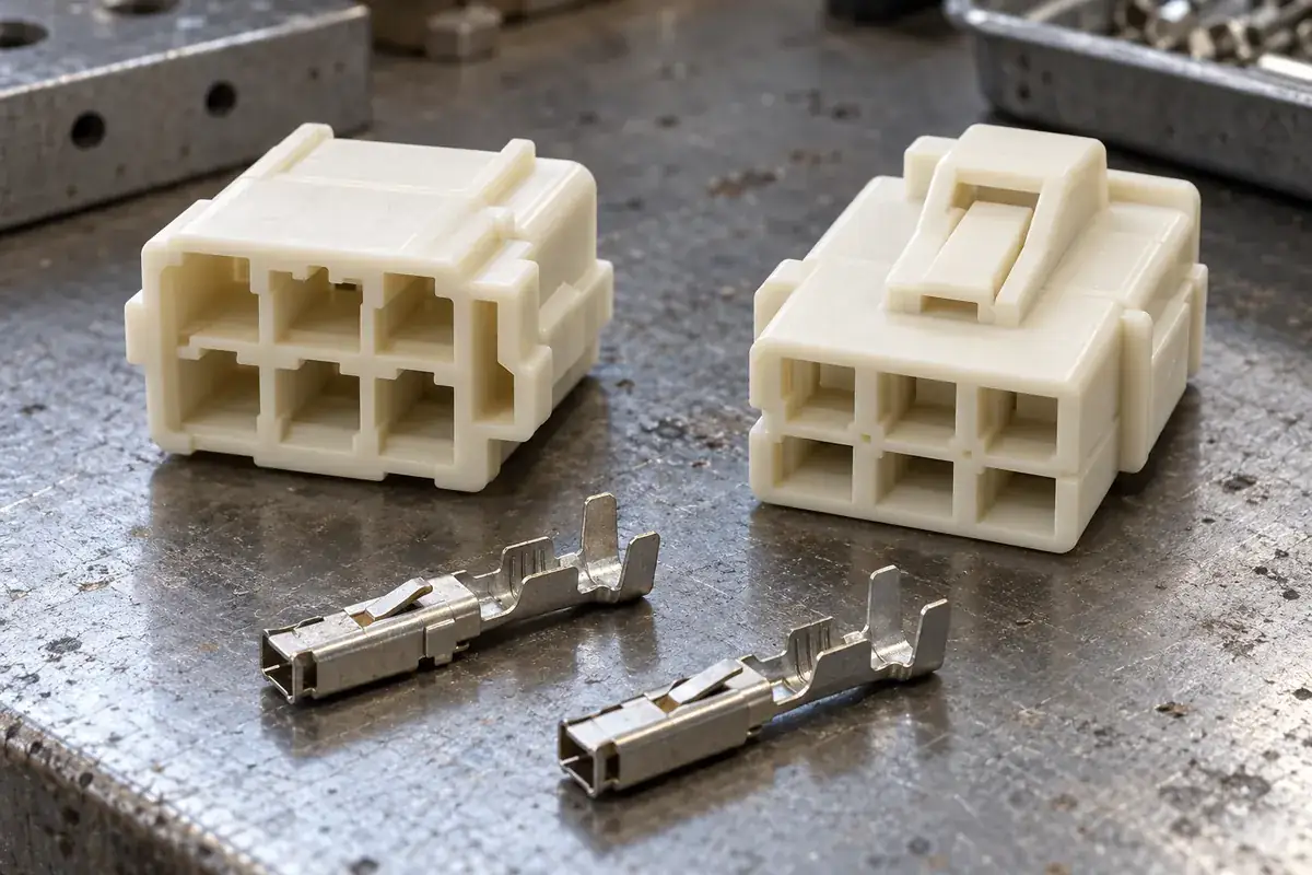
The wire has been assigned to the correct cavity, but its terminal still refuses to seat. Circuit numbering answered where the wire belongs; it did not answer which way the terminal must face. In a crimp housing, those are separate decisions, and a drawing that describes only the circuit order can leave the most important assembly orientation implicit.
Good orientation control begins with the contact's physical asymmetry. A retaining lance, locating shoulder or formed guide feature may require a particular relationship to the molded cavity. The housing should support that relationship along the loading path, while markings and assembly references help identify the cavity. Neither function can reliably substitute for the other.
Product design illustrations accompany the assembly and manufacturing explanations below.
Keep three kinds of direction separate
First consider the rotation of an individual contact as it enters its cavity. Its contact box can appear nearly symmetrical while a small lance on one side determines the valid orientation. A wire naturally curving to the left or right is not a dependable reference for that feature, particularly after the wire has been cut, stripped and crimped.
Second consider cavity identity. The harness drawing assigns circuits to locations in the housing, often using a particular viewing direction. A cavity map viewed from the mating face is not the same picture as one viewed from the wire-entry face. Make the reference view explicit so a correctly oriented contact is not loaded into the mirrored location.
Third consider polarization of the assembled housing against its board-side counterpart. A large exterior rib may prevent the housing from mating upside down while doing nothing to stop a loose terminal from entering incorrectly. Treat contact orientation, circuit position and housing polarization as separate layers in the assembly definition and verify each with the relevant component drawing.
Make the guide act before the wrong feature is loaded
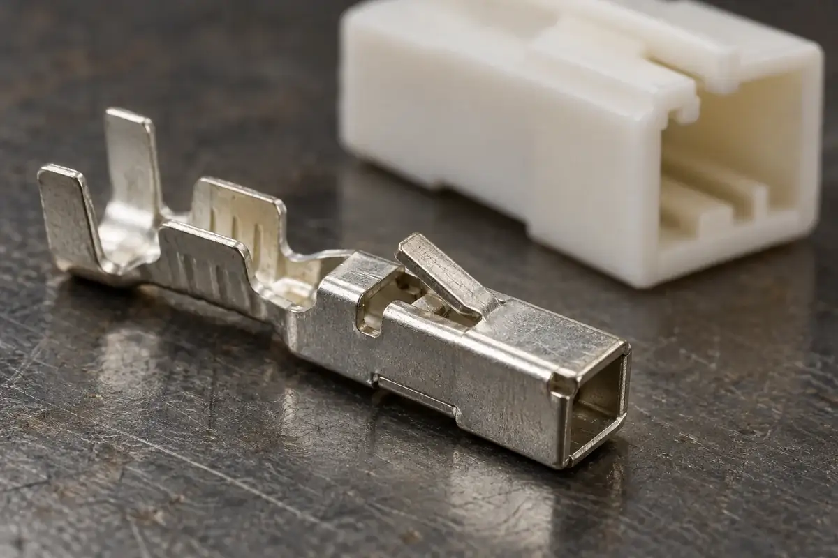
A guide is most useful when it establishes orientation early enough to protect the retaining and contacting regions. If an incorrectly rotated terminal travels deeply before meeting an obstruction, the assembly process may already have loaded a fragile lance or contact spring. Review the approach sequence, not just the final shape shown in a seated cross section.
A narrow keyed entrance can reject an incorrect contact orientation but also make correct assembly sensitive to presentation angle. A broad lead-in can improve entry but must not bypass the orientation feature. The design trade-off is between useful guidance and unnecessary restriction, evaluated with the actual terminated contact rather than an idealized rectangular block.
Review the relevant tolerance directions together. Variation in a folded contact shoulder, molded guide notch and approach angle can accumulate at the same point. Increasing clearance at one wall may help correct entry but weaken the distinction between valid and invalid orientations. Use the paired geometry to decide where clearance is beneficial and where a deliberate obstruction is necessary.
Keep mold manufacturability connected to that function. A thin guide detail requires a viable steel feature, adequate support and a release path. Moving the guide to a more robust location may be preferable to demanding a fragile detail merely because it looks neat in a section view. The objective is repeatable orientation control over the component's intended supply life.
Use markings to communicate what geometry cannot
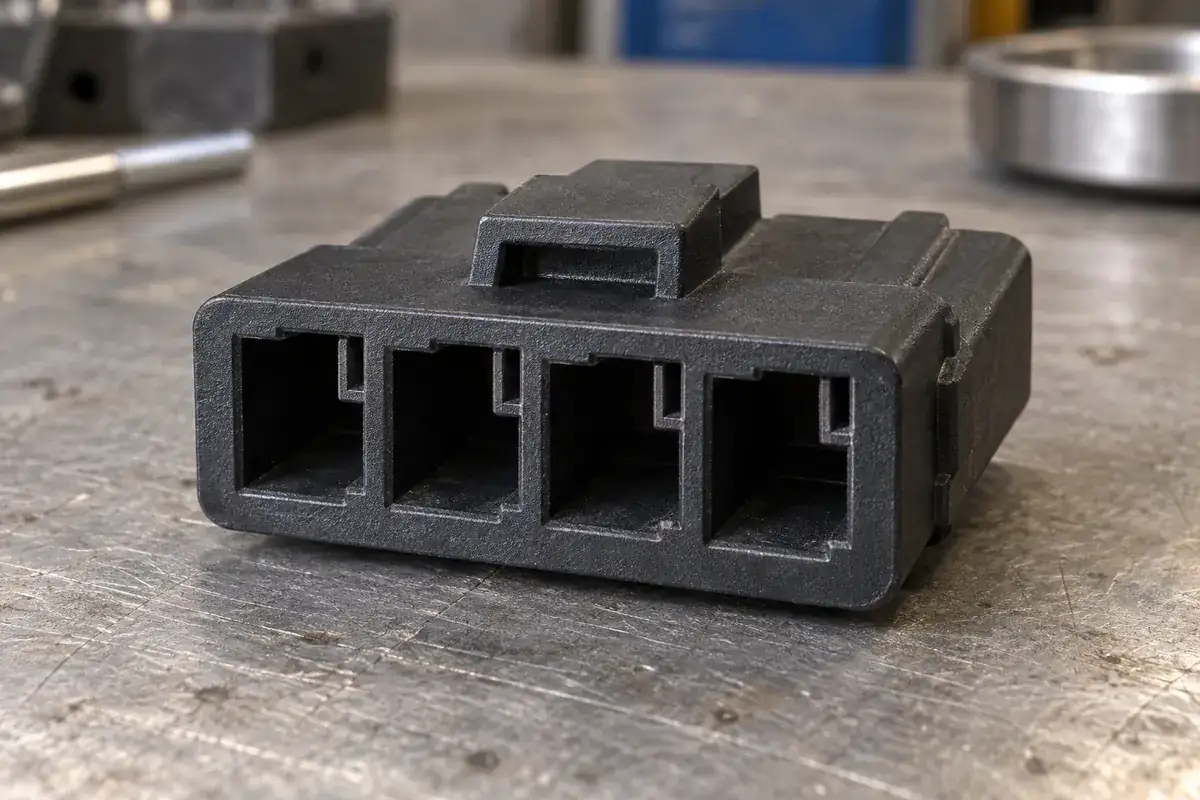
Cavity numbers, color and an exterior reference feature can help identify a circuit location, but their visibility depends on the assembly stage. A mark visible before loading can disappear behind wires or a cover afterward. Decide which reference remains available when the operator needs it, and show that same reference in the harness drawing and inspection instruction.
The JST PH connector drawings identify a first-circuit reference and specify the view used for board layouts. This illustrates why view direction and location references should be stated explicitly. It does not establish a universal numbering convention for other connector families or a custom component.
Do not infer wire identity from housing color alone unless the assembly specification assigns and controls that meaning. Color can support recognition while still being shared across variants. A mechanical key can prevent one kind of mismatch, whereas a circuit map addresses electrical assignment. Keeping their roles distinct makes a change review much clearer.
Service work creates a second audience for these references. A technician may see only the rear face and a partially released contact. If the approved release method requires a particular contact orientation or tool entry, provide a reference that survives disassembly. That is more useful than relying on a production fixture that will not be present in the field.
Evaluate both correct loading and plausible errors
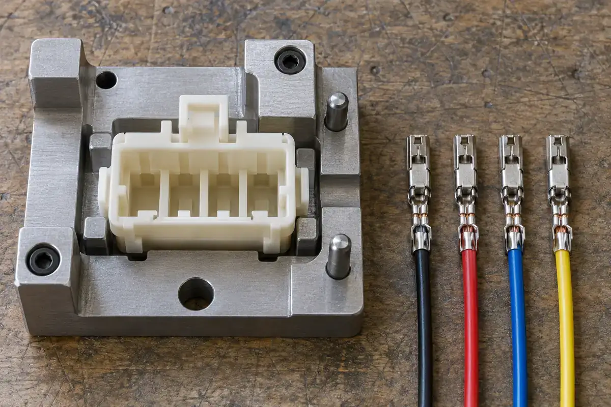
An assembly review should include normal loading with the expected wire handling and fixture arrangement. It should also identify plausible errors such as a rotated contact or reversed viewing reference. Determine how those conditions are detected before damage occurs. The design team should define the permitted evaluation method rather than treating forced misassembly as an informal durability test.
Observe whether a contact can appear seated while missing its intended retention relationship. A flush wire-side appearance does not necessarily reveal the position of an internal lance. Establish an appropriate seating and retention verification for the chosen contact system. The related insertion-interference guide helps separate a blocked path from a correctly engaged stop.
Consider how neighboring wires change the presentation angle as the housing fills. A guide that works with the first contact may be difficult to approach once a bundle occupies the rear area. This connects orientation control to wire routing and available bend space, rather than making the cavity detail carry every assembly burden alone.
When reviewing custom wire-to-board housings, supply the terminal drawing, circuit map and counterpart orientation together. Define the valid loading direction, the reference view and the features used to confirm seating. Those details let the molded guide and the assembly instructions reinforce one another without confusing correct circuit assignment with correct mechanical engagement.