
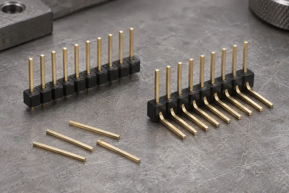
A right-angle header can look simple once it is complete: a plastic strip locates the posts, and each post turns toward the board. During manufacture, however, someone must establish the bend, position the plastic and preserve the lengths on both sides. Changing the order of those operations changes which features the tooling can reach and which parts receive the forming load.
There is no universal rule that every header should be bent first or assembled first. The contact construction, forming method, retention arrangement and required geometry decide what is practical. The right question is which sequence can create and inspect the intended assembly without relying on a weak plastic edge to perform the job of a forming tool.
Product design illustrations accompany the assembly and manufacturing explanations below.
Define the finished geometry before choosing the route
Identify the mating length, the board-side tail position, the bend location and the plastic seating reference. A nominal bend angle alone does not fix the endpoint: the bend's location and shape also affect where the tail lands. The assembly drawing should make clear which surfaces and axes are functional and how the completed component will be located for inspection.
Samtec's TSW range includes vertical and right-angle square-post configurations with different lead options. The range demonstrates why the configured drawing matters. The existence of both orientations does not establish a particular factory forming sequence, and the manufacturing route for a custom base must be evaluated independently.
Clarify whether the contact enters a previously molded base, is retained by a separate feature or is incorporated through an insert-molding process. Those constructions offer different access and restraint. This discussion concerns the decision around contact forming and base placement; it does not assume that every pin header is assembled by pressing loose pins into finished plastic.
Include the approved contact material and finish in the review. Forming behavior and permitted handling depend on the metal definition and its condition. If forming occurs after plating, the finish at the bend and tool contact areas needs evaluation under the supplier's requirements. A plastic drawing cannot answer those metal-process questions by itself.
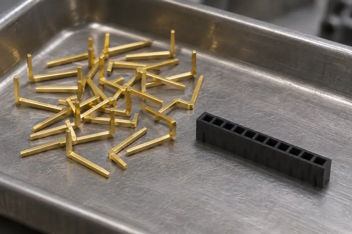
Bending first changes the insertion and feeding problem
With a preformed contact, the metal forming operation can be developed without the plastic body immediately beside the bend. The forming tool may have simpler access to the supported metal section. However, the resulting L-shaped part must then be oriented, guided and inserted without its second leg colliding with the base, fixture or neighboring contacts.
A bend can provide a useful visible orientation reference, but it should not automatically become the insertion stop. If the process seats the bend against plastic that was not designed as a bearing surface, normal variation in the formed shape can change the final contact position. Decide which feature locates the metal and which feature merely provides clearance.
Feeding also deserves attention. A loose straight post and an L-shaped contact behave differently in trays, tracks and transfer tooling. The process must keep the required orientation through the last guided part of insertion. For multi-row headers, the formed legs may require a particular loading order so that an earlier row does not block the next one.
Inspect the preformed contact before it is hidden by the base. This can separate a metal-forming issue from a later assembly issue. Keep the measurement references consistent with the final design, and check whether inserting the contact changes the previously accepted geometry. A good loose contact can still be bent out of position by an unsuitable installation method.
Installing the base first changes the reaction path
A straight contact array can be easier to guide during initial base installation, but forming the exposed section afterward introduces a new load case. The forming reaction must be controlled at the appropriate metal surfaces. If the tooling instead pushes against the base edge, the operation can rotate the retained contact, crack a thin wall or move the plastic along the post.
The tool needs access near the intended bend while leaving space for the plastic and already formed contacts. A base that covers too much of the metal may obstruct that access. Reducing the base locally can restore access, but the change must be checked against contact support, retention and the available electrical and mechanical boundaries.
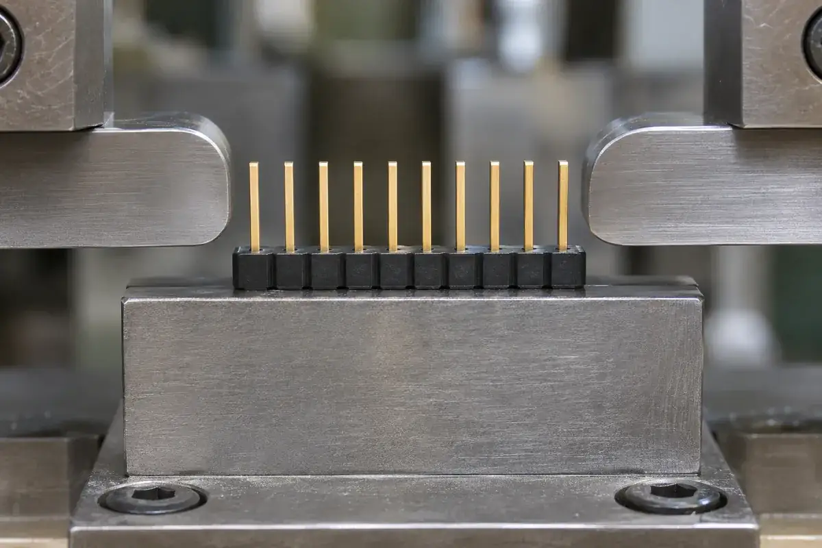
Do not use the mating tip as an improvised handle for correcting a formed contact. Such an adjustment may change the bend location or damage a surface that later engages the socket. If correction is permitted, define the supported region, tool and acceptance checks as part of the process. Repeated manual bending is not a substitute for controlling the original operation.
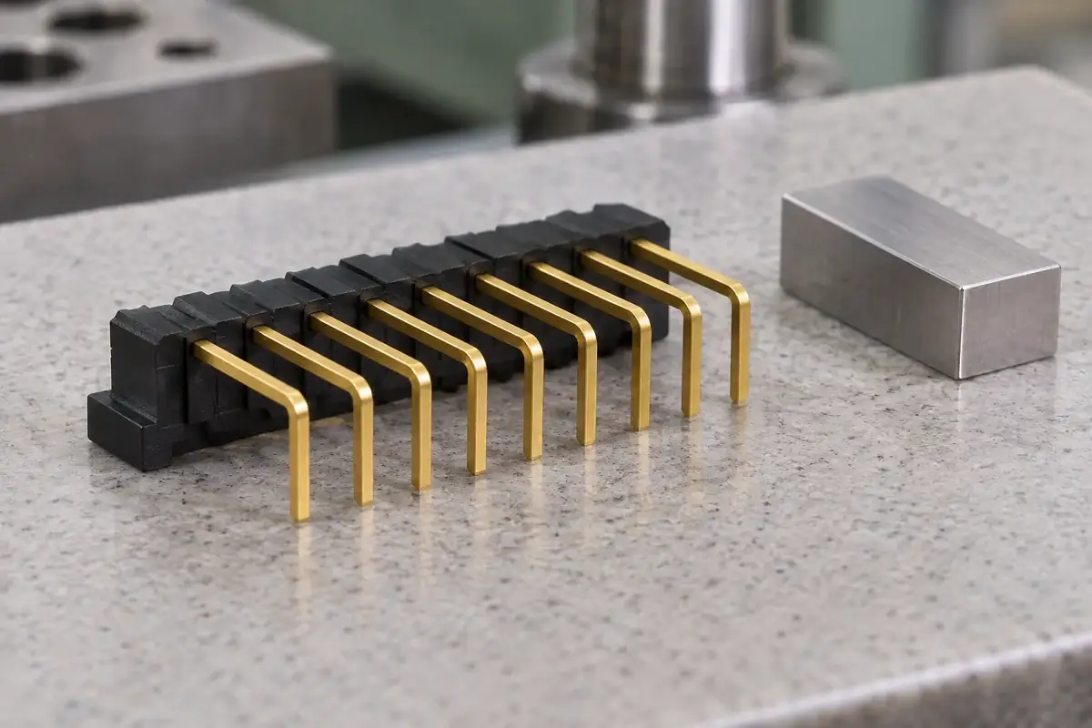
A completed right-angle header should be inspected after it leaves the forming fixture. Restraint can hold an array straight while concealing residual movement. Check the plastic position, the tail pattern and the mating ends against their respective references. The connector datum inspection guide explains why the chosen reference must follow the functional interface.
Choose the sequence that can be controlled and maintained
Compare proposed routes using more than the number of machine steps. Consider the amount of exposed metal available for support, part orientation during transfer, access for inspection and the effect of a rejected contact on the rest of the assembly. A route with fewer operations can be more difficult to maintain if each operation depends on a delicate intermediate state.
Use the sample plan to evaluate the route as a sequence. Identify the contact and base revisions, inspect relevant intermediate states and compare the final assembly with the agreed drawing. Do not set a universal bend radius, forming force or plastic clearance from appearance. Those values depend on the contact design, material and the selected manufacturing method.
For custom pin-header and socket insulator bases, share the intended contact-forming route alongside the component model. We can review the plastic features with the installation support arrangement and tooling access, so that the base helps establish the final assembly instead of becoming an unintended forming stop.