
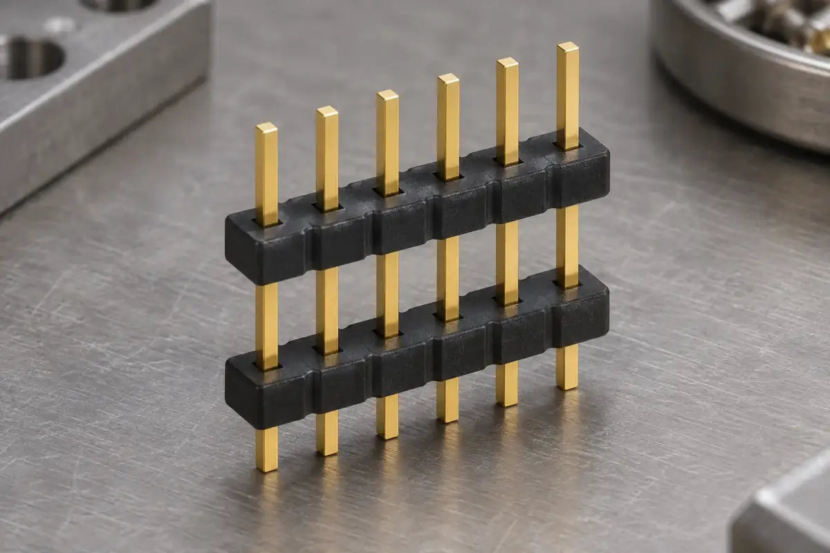
Two plastic strips on the same pin array can appear to solve alignment automatically: the first holds one section of the posts, and the second holds another. In practice, each strip introduces another hole pattern and another locating interface. If those patterns do not agree, installing the second body can bend the pins or leave the assembly carrying stress before it reaches the PCB.
A dual-insulator design therefore needs more than a nominal distance between bodies. Define where each body sits along the contacts, how the patterns align and which references establish the exposed lengths. The separation of the two insulators is one component dimension; the final spacing between connected circuit boards also depends on the mating socket and its mounting arrangement.
Product design illustrations accompany the assembly and manufacturing explanations below.
Give both insulators a functional reference
Identify the purpose of each body. One may establish the board-side support while the other provides a guided region nearer the mating end. Another design may use both as intermediate supports on long posts. The intended function determines which face, hole section and axial position need to be controlled, rather than assuming both strips have identical roles.
Samtec's explanation of configurable stacking connectors describes setting body positions on header strips and dual-body stackers. The useful distinction is between a specified body position and the overall mating arrangement. Those positions are controlled manufacturing options, not a suggestion that an assembled insulator should slide freely during use.
Specify the axial chain using references that can be inspected. If both bodies are positioned independently from an arbitrary pin tip, variation at that tip can affect both measurements. Depending on the design, it may be clearer to reference one body and establish the second relative to it, while separately controlling the exposed contact lengths. Choose the scheme around the functional assembly.
Apply the same care to lateral location. Overall strip width may be convenient to measure, but it does not establish the relationship between two hole arrays. Determine how the hole pattern is located relative to the references used by the fixture and the mating component. The pin-pitch datum guide explains why the outer envelope and the contact pattern answer different questions.
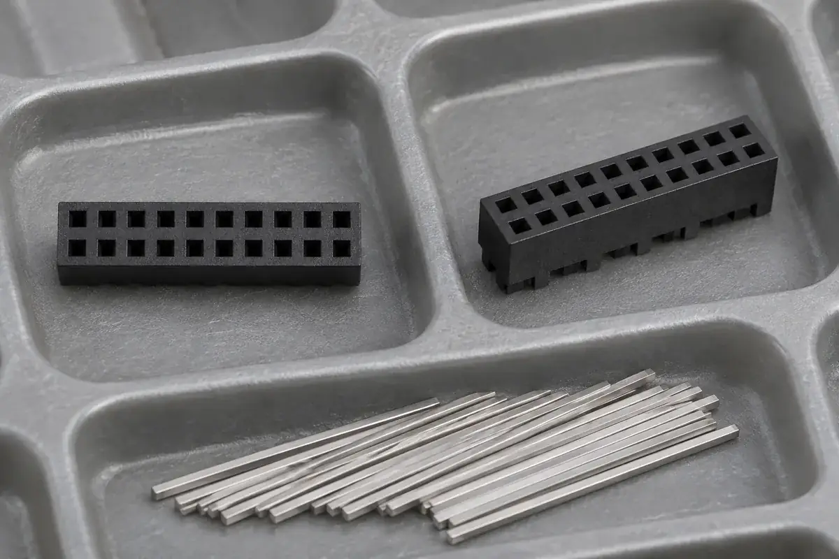
A second body can support pins or force them out of line
When the second insulator is installed, each post must enter its corresponding opening along a practical path. A small mismatch at one location may be accommodated by local deflection, while several mismatches across a long row can produce a different overall distortion. Evaluate the pattern as an assembly, including end positions, instead of checking only a convenient central hole.
Do not use the pins to forcibly straighten a warped plastic strip unless that restraint is an intentional, evaluated part of the design. A clamped assembly can look straight during installation and change shape after release. It can also transfer a molding variation into the contact array, creating a mating problem that appears to be a metal-forming issue.
The local entry and retaining sections need separate review. An opening may guide the post freely at its mouth but constrain it more strongly farther inside. If the two bodies retain the same contact at different axial locations, confirm that their intended engagement does not require incompatible movement during installation or later processing.
Longer exposed posts also make handling more consequential. Transport trays and transfer grippers should support the intended bodies or approved contact regions without pushing the array sideways. Adding a second body does not make every exposed section rigid, and a packaging pocket designed for a single short base may contact the new assembly in the wrong place.
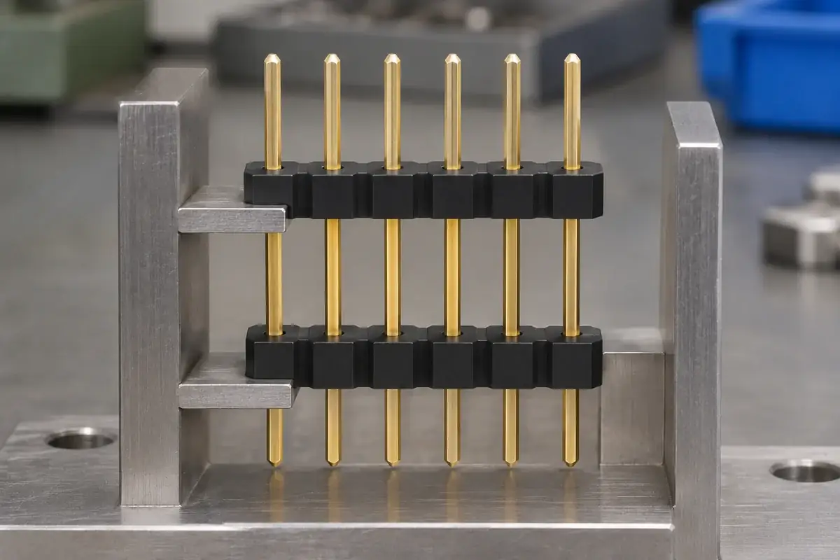
Set the assembly height without hiding misalignment
Review how the tooling establishes the second body's final position. A fixture can locate the first body, guide the second and provide a controlled stop, but those features must allow the real components to seat without excessive restraint. If the stop acts on an uneven or incidental plastic detail, the measured separation can change even when the machine stroke is repeatable.
Provide clearance for the post ends throughout the operation. A tail that touches the fixture floor can become an unintended height reference, and an overlong mating end can encounter the tooling before the body reaches its stop. Both conditions can make a contact appear seated while the plastic-to-plastic distance remains wrong.
Check parallelism and position after the assembly leaves the nest. The relevant question is whether the two bodies and the pin array remain in the required relationship without the fixture holding them there. Use an inspection approach that can reveal tilt across the strip as well as average separation; the same average gap can conceal opposite errors at the ends.
Do not force the completed array into an overly restrictive gauge and treat the resulting fit as proof of its free-state geometry. A functional gauge can be useful when its purpose and insertion conditions are defined, but it may also straighten flexible posts. Pair the agreed functional check with the dimensional observations needed to understand the unrestrained assembly.
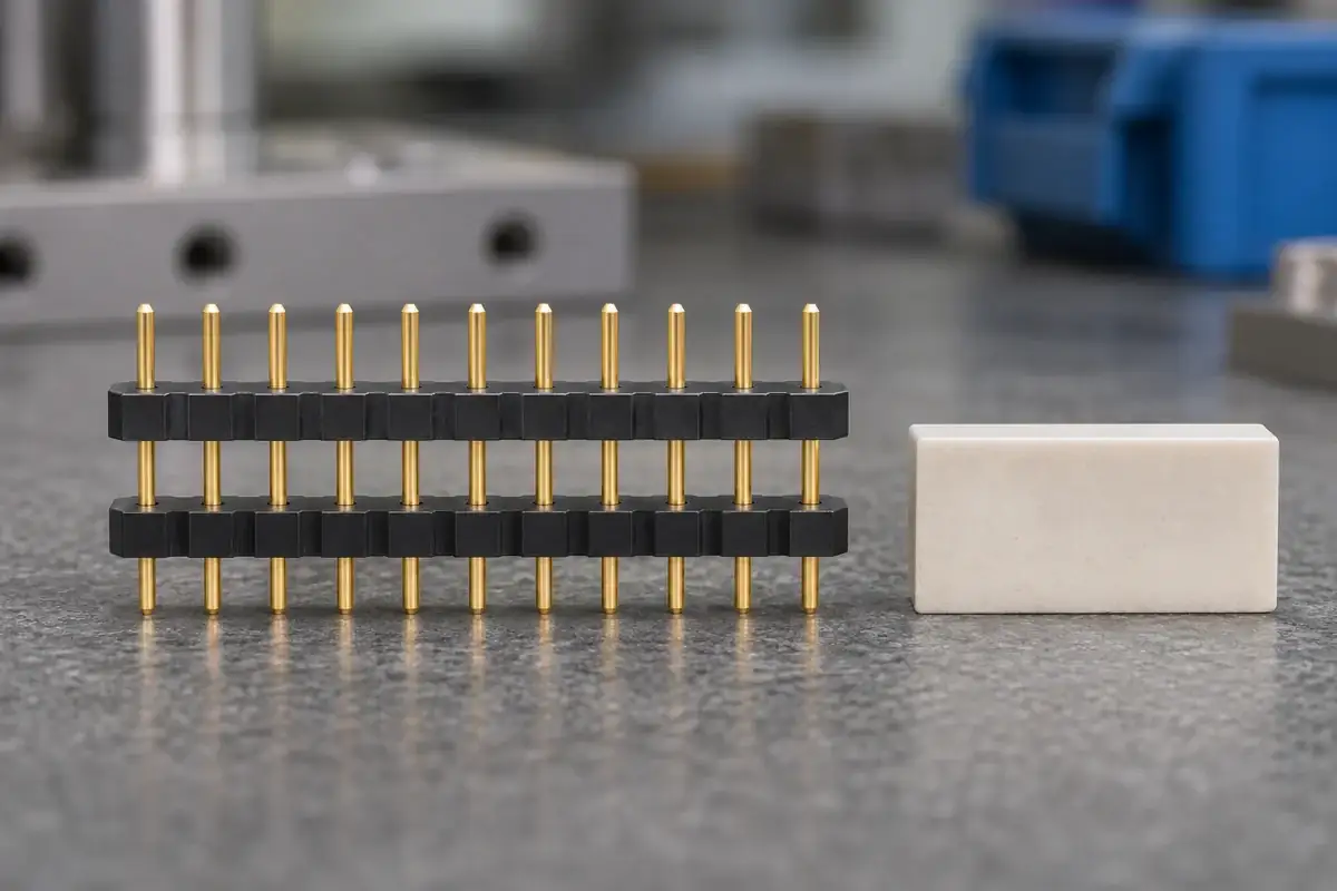
Keep the component dimensions separate from board spacing
The board-to-board distance comes from the complete mated system. It includes the socket interface, contact engagement and the way each connector mounts to its board. The distance between two plastic strips on one header is only part of that relationship. Use the mated stack-height review when checking the surrounding electronics layout.
Where several heights share a molded strip, maintain a controlled assembly definition for each variant. A shared plastic tool does not make the pin lengths, body positions or packaging interchangeable. The sample and inspection plan should identify the exact variant and the contact definition used, particularly when a common-looking strip is installed at different axial positions.
For custom dual-insulator bases, provide both plastic bodies, the full contact drawing and the intended assembled condition. Reviewing them together allows tooling, location and inspection to follow the same references. That is the practical route to an array that remains aligned after release and arrives at the mating operation in the intended condition.