
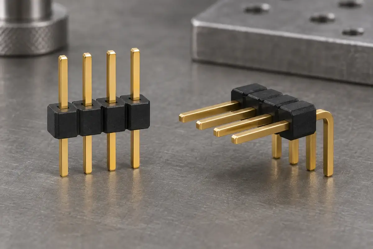
Changing a header from vertical to right-angle does more than redirect the mating face. It changes where the contact bends, where the plastic supports it and how assembly forces reach the board. A base that works well around a straight post may provide little support at the location that matters after the contact is bent.
The useful comparison follows the contact from its mating end to its termination. Note each unsupported length, each plastic contact region and each surface used during installation. That reveals whether a proposed feature is guiding a pin, resisting its movement or merely occupying space. The same comparison also helps separate a connector problem from a fixture or enclosure-access problem.
Product design illustrations accompany the assembly and manufacturing explanations below.
Follow the direction of force through the contact
With a straight header, the mating direction may be broadly aligned with the pin axis. The actual reaction still depends on the socket, the board support and the way the assembly is held. If the plastic body is supported while a pin is pushed axially, the retention interface sees a different load from one produced by pushing the board or pulling an exposed pin sideways.
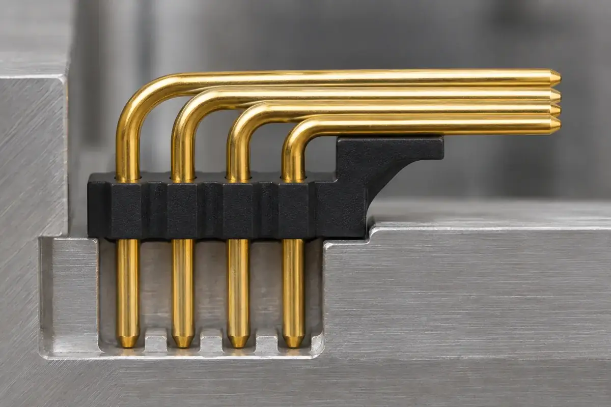
A right-angle contact introduces a bend between the mating portion and its board termination. The mating force can act at a distance from the region that supports the contact. That distance can create a turning effect around the support. Review the geometry and load path before assuming that a thicker strip will solve movement at the bend.
Samtec's TSW range includes vertical and right-angle orientations within the same header family. They are specified configurations, not an invitation to bend a finished straight header into a new shape. For a custom component, the contact forming process and its final supported geometry need their own definition.
A longer free segment can improve reach to a mating connector, yet also increase the opportunity for displacement during handling. A support moved closer to the mating end can reduce that free length, but may conflict with socket entry or reduce the usable engagement length. Compare both effects in the assembled section rather than optimizing support in isolation.
Choose the plastic reference that assembly can actually use
For a straight strip, the lower plastic face may provide a convenient seating reference against a board or assembly fixture. That face only works as intended if molding variation, flash and local feet are included in its definition. A broad nominal face with a few unintended high spots can tilt the strip while its overall height appears acceptable.
For a right-angle header, the horizontal mating axis must be related to the board plane. The base may need a lower ledge, separate seating pads or another defined reference. The feature should be evaluated with the formed contact installed, because the bend position and contact seating can change the axis even when the empty plastic part measures correctly.
Do not confuse a board locating peg with contact retention. A peg may help place the whole connector on a footprint while doing little to resist movement of an individual pin within the base. Likewise, a molded rib near a bend is not automatically a load-bearing support. Identify the contact condition and permitted gap for each feature before assigning it a role.
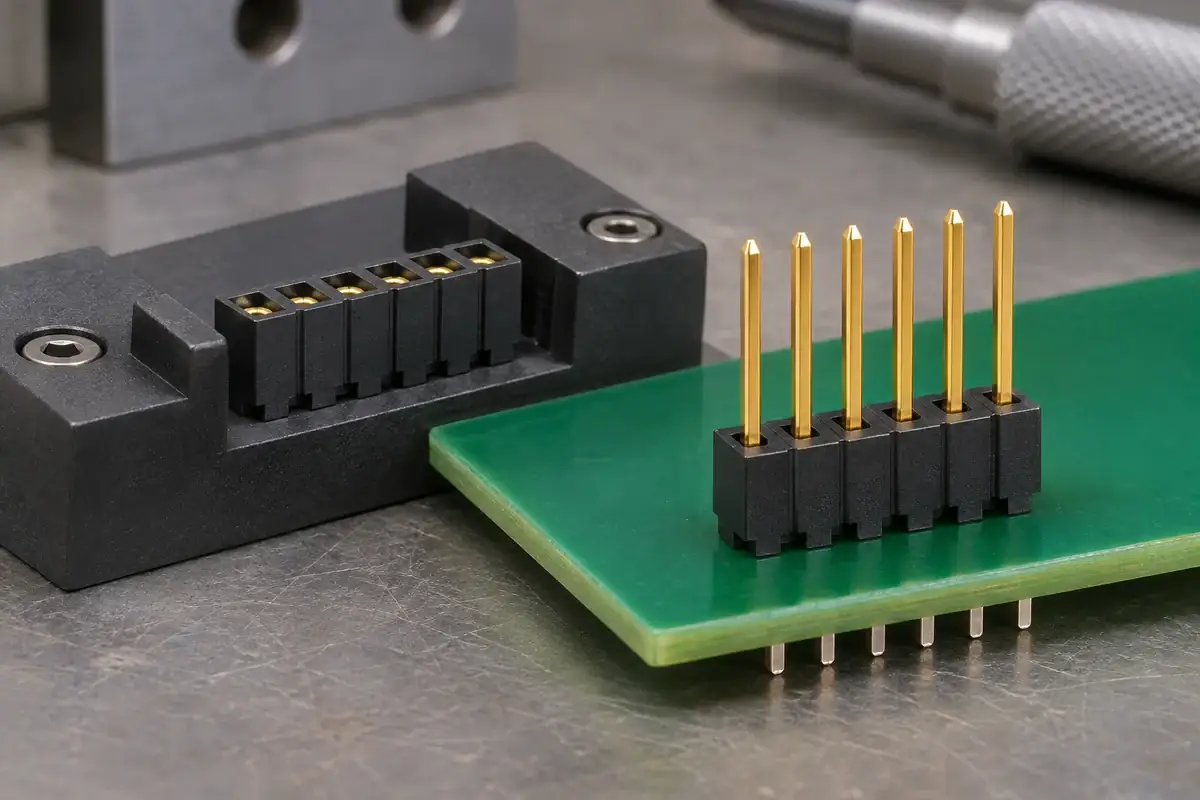
Our guide to header and socket insulator functions separates pin support from receptacle action. Use that distinction when comparing mating halves: a right-angle base should present the intended pin position to the socket, while the socket contact must retain its own designed movement and receiving space.
Review the installation and service approach
A vertical connector may be easy to approach from above but inaccessible once another board or cover is installed. A right-angle connector can move the mating action toward an enclosure edge, although that may place the grip area close to neighboring components. Evaluate the complete installed assembly, including the space needed to remove the mate without levering against the pins.
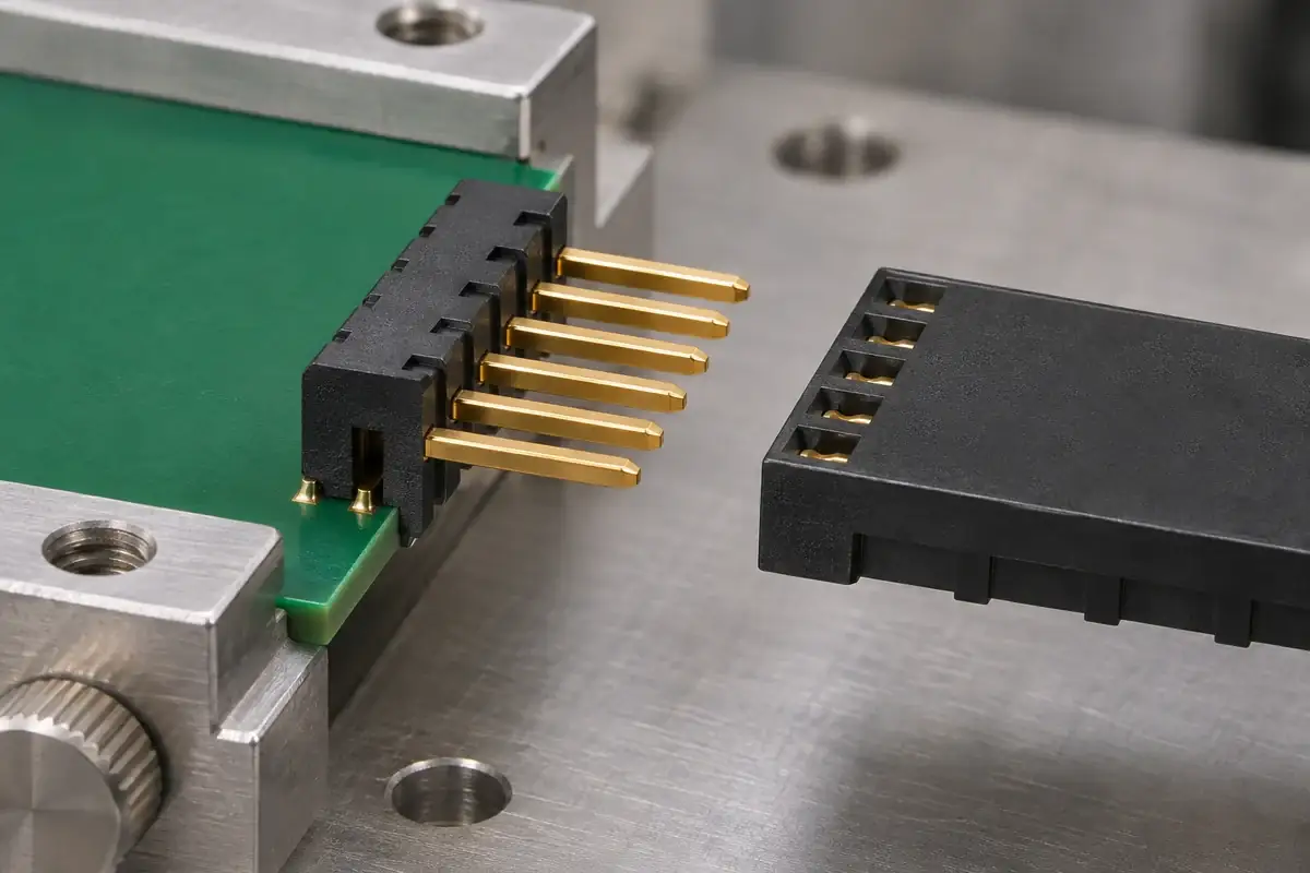
During board installation, the force application point should be compatible with the connector construction. Pressing on the horizontal ends of a right-angle header can load the bends rather than seat the plastic body. The fixture review should define a practical contact surface that transfers the intended installation load without relying on an unsupported pin segment.
Board fastening is another part of the support system. Samtec's socket-and-terminal-strip specification recommends mechanical standoffs for robust board-to-board support. For a custom arrangement, agree how the boards are supported and how mating is performed; the connector should be evaluated in that defined mechanical arrangement.
Packaging should reflect the chosen orientation as well. Projecting right-angle pins can catch a tray edge during removal, while long vertical pins can be bent by a shallow cover. Define the protected envelope and handling direction around the finished component. A packaging change can alter the loads seen before assembly even when the molded base itself is unchanged.
Compare design changes with identified assemblies
Begin a comparison with controlled contact and plastic revisions. Record the bend location, the installed body position and the final board seating arrangement. If these vary between samples, a difference in apparent rigidity cannot be assigned confidently to the new support feature. Inspect the molded component separately, then evaluate the completed assembly that it is intended to support.
Choose observations that answer the actual concern. If the mating end moves, determine whether the pin flexed, the pin shifted within the plastic, the base tilted or the board moved. Those mechanisms call for different changes. Making the whole base larger may hide one symptom while leaving the original interface inadequately controlled.
Tooling feasibility belongs in that review. A support near a bend may require narrow cores, additional parting-line decisions or access that is unavailable after the contacts are installed. The article on pin bending and base assembly sequence examines how the order of operations changes the surfaces available to both forming tools and plastic supports.
For custom header and socket insulator bases, provide straight and bent contact models where relevant, the mating direction and the intended board references. Include the handling and installation method with the dimensional drawing. Those details let the molding proposal address the support positions that influence the real assembly instead of reproducing an outline alone.