
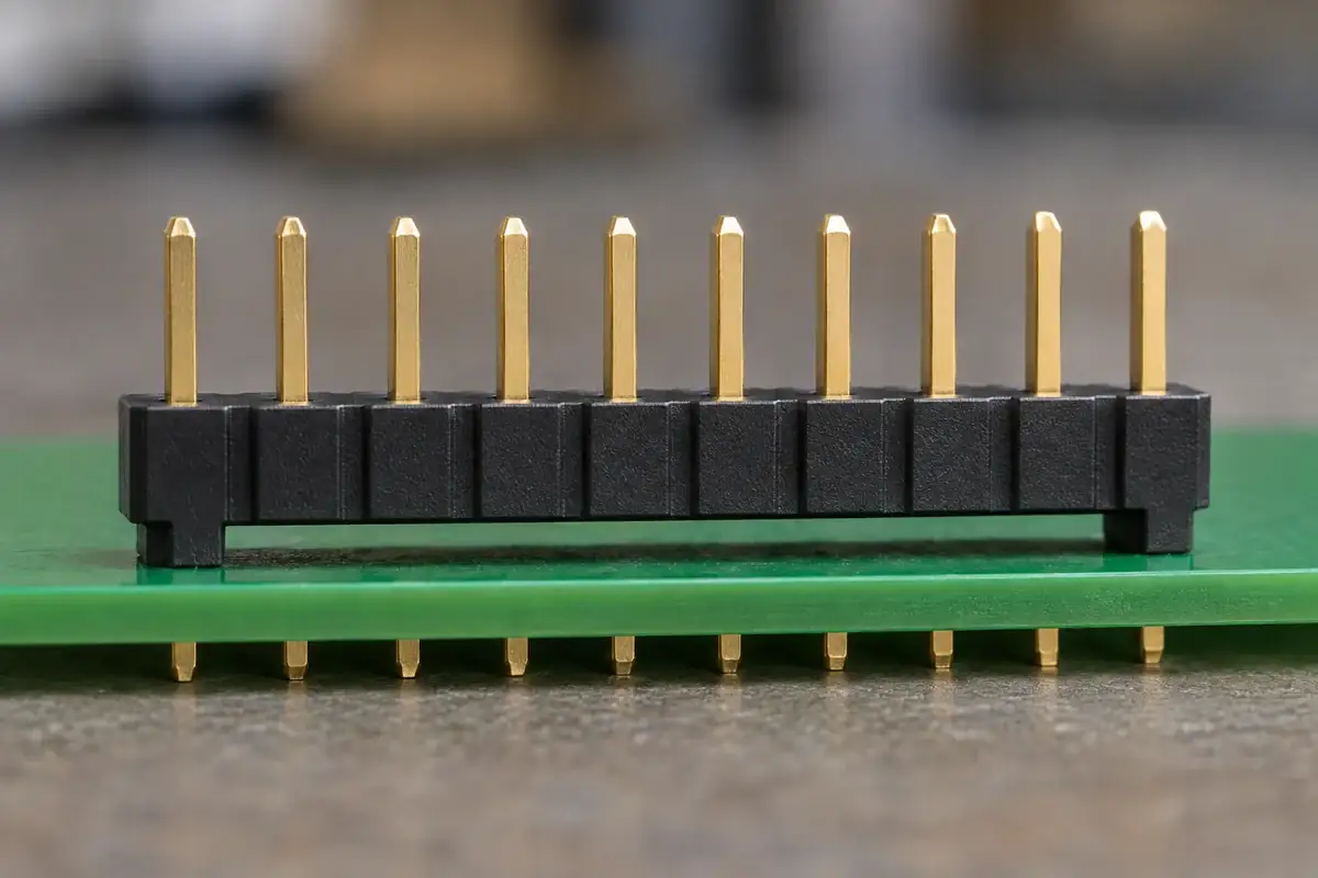
A pin header may have the correct pitch and fit the PCB holes yet sit differently from the intended design. One version rests on molded feet, another appears to sit on the full underside, and a third rocks before soldering. These differences affect where the tails emerge, how the component is supported and which spaces remain accessible during processing.
The board standoff is the intended relationship between the insulator and the board surface, established by the features that actually touch. It is not the same as the exposed mating-post length or the final distance between two connected boards. Treating those dimensions as interchangeable can solve a cleaning-access problem while creating a tail-projection or mating-height problem.
Product design illustrations accompany the assembly and manufacturing explanations below.
Identify what sets the distance above the board
Start with the bearing features. Integral feet, separate spacers, formed contact geometry or another approved feature may establish the base position. Determine which are intended to contact the PCB and which require clearance. The lowest visible plastic detail is not necessarily the designed support, especially if a gate vestige or an incidental molded feature lies nearby.
Review the PCB surface as part of that interface. Pads, solder mask, nearby components and the board's local flatness can affect seating. A foot located partly on a pad and partly on surrounding material may not establish the same reference as a foot placed on the intended uniform area. The component and board definitions need to agree on the contact locations. Check whether a support foot can bridge a local surface change and leave the neighboring feet unloaded before the assembly is soldered.
Samtec's SMT handbook discussion of standoffs links access beneath an insulator to board cleaning and solder-joint inspection, and discusses support for small surface-mount leads. Its dimensional guidance belongs to that SMT context. It should not be converted into a universal minimum gap for every through-hole pin header or cleaning process.
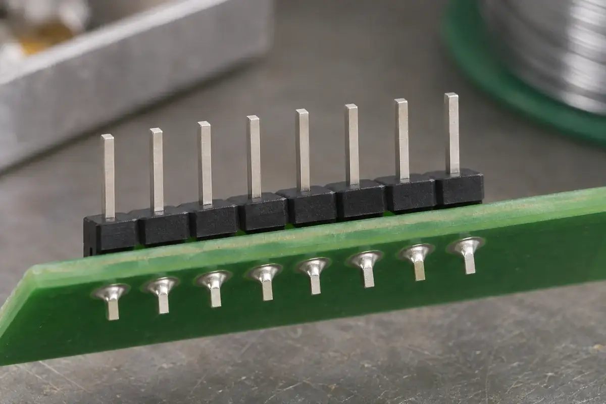
For a through-hole design, changing the distance above the board also changes how much of a fixed tail remains available below it. Check the complete relationship between contact length, base position, board thickness and required termination geometry. Adding taller feet without revisiting that chain can leave an otherwise unchanged contact with an unsuitable solder-side projection.
Keep support and soldering access in the same review
A larger open gap can improve access in one direction while reducing support close to the contact row. The base still has to remain stable during placement, board handling and the specified soldering operation. Consider where the part can rock or tilt before the joints are complete. A tall foot is useful only if its location and contact area provide a controlled seating condition.
Through-hole and surface-mount arrangements need different checks. A through-hole tail enters a hole and is assessed against the approved hole, pad and soldering requirements. A surface-mount lead rests at a pad and depends on the intended lead geometry and placement condition. Do not use an insulator height adjustment to compensate for an unsuitable lead or board pattern.
Look at the soldering method and tooling access rather than assuming the same underside opening serves every process. Fixtures and selective-solder tooling can restrict access from below, while neighboring parts can obstruct access from the side. The approved assembly process determines which regions need room and which surfaces must remain supported.
Joint visibility is another practical consideration. A base that closely covers the contact region can make inspection more difficult, but opening a view does not by itself establish an acceptable solder joint. Agree the inspection method and acceptance requirements for the actual board assembly. Keep the plastic's dimensional inspection separate from the evaluation of the completed termination.
A cleaning path needs an entrance and a way out
When the assembly requires cleaning, trace the space beneath the base as a connected path. A visible opening along one edge may lead into a pocket bounded by feet, walls and the dense pin array. Assess whether the selected process can reach that region and remove the resulting liquid or debris. A side-view gap alone does not describe the full geometry.
The pin arrangement matters. Closely spaced rows can divide the underside into narrow passages even when the outer perimeter looks open. Support features should be reviewed against those passages rather than added wherever unused surface appears available. The board orientation during washing, rinsing and drying can also affect which regions are easiest to access.
Cleaning chemistry, flux choice and material compatibility belong to the process review. A geometric opening cannot make an unsuitable chemical compatible with the resin or contact finish. Where cleaning is not part of the approved process, avoid assuming that a different flux system removes every need for residue assessment. Use the assembly requirements to determine what must be evaluated.
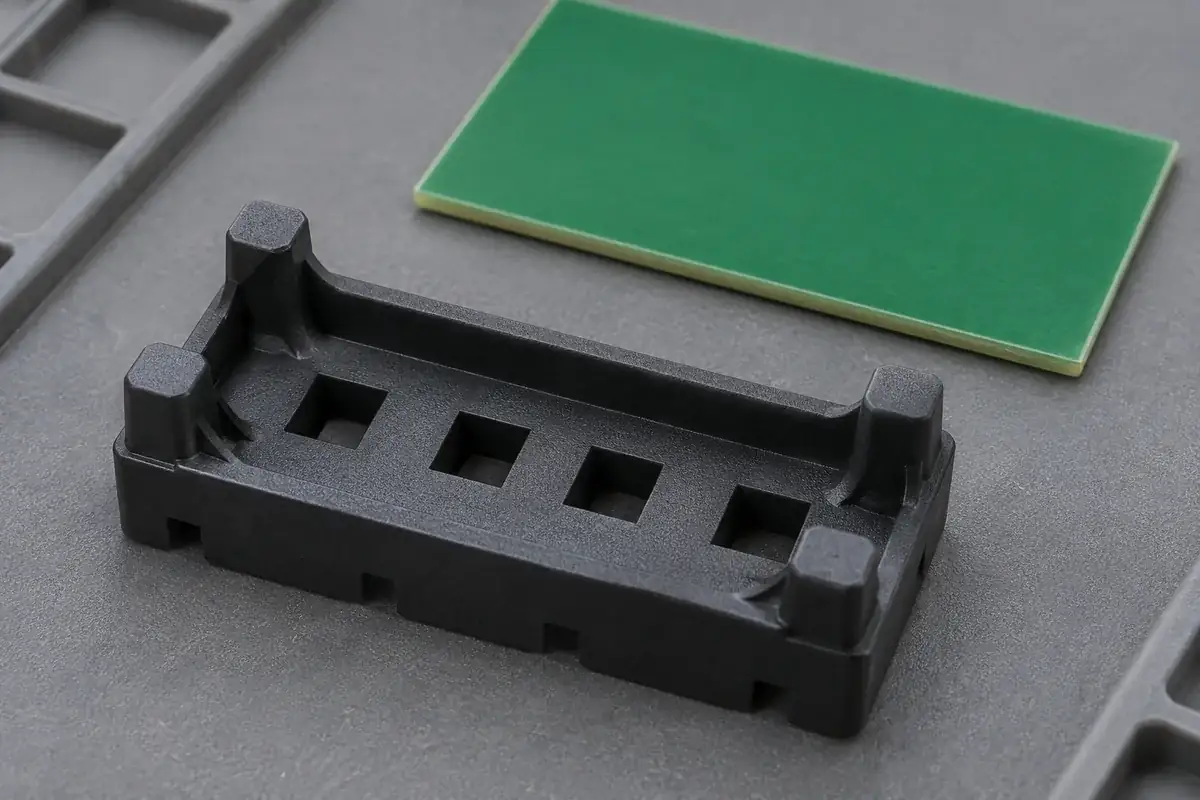
Inspect representative assemblies after the actual process stages. An empty base on a loose PCB coupon can help explain the space, but it does not reproduce populated-board obstructions or the soldered contact array. Include the relevant surrounding features when evaluating access, drying and the ability to inspect the region beneath the component.
Change the support features with a complete dimensional check
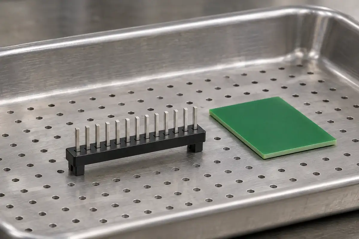
If a revised standoff improves access, revisit the mating end as well as the board end. Raising the base may change the relationship to a socket, enclosure opening or neighboring component even when the metal contact itself is unchanged. Our board-to-board stack-height guide addresses that larger assembly relationship.
Define the bearing faces, their permitted variation and the contact configuration used for approval. Confirm that the selected plastic and molding process can produce the feet without fragile edges or uncontrolled local distortion. The tooling review can also consider whether a gate or ejection feature would intrude on the agreed support surface.
For a custom pin-header insulator base, send the contact drawing, PCB interface and proposed soldering and cleaning sequence with the plastic model. This makes the standoff a controlled assembly feature, tied to support, tail length and process access, rather than an isolated gap chosen from a catalog photograph.