
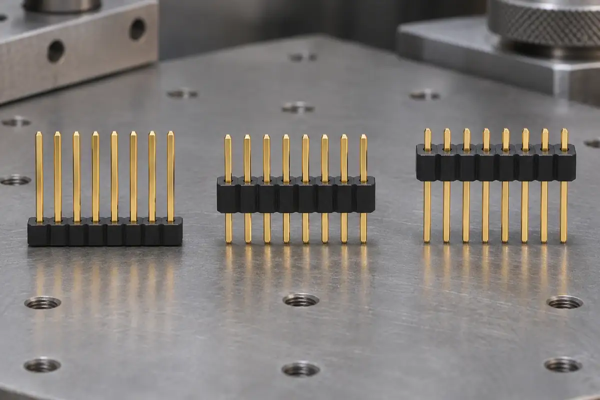
Two headers made with the same total pin length can present different lengths to a mating socket. The difference may be the height of the plastic strip, its position along the pin, or the reference used when the assembly is measured. Ordering a longer pin without resolving those relationships can move the problem from inadequate mating engagement to an excessive solder tail.
Exposed length is a result of the assembled geometry. Before changing a contact or a mold, distinguish the portion above the mating-side plastic face, the portion below the board-side face and the position of those faces in the finished equipment. That separation makes it possible to find where the unwanted variation begins.
Product design illustrations accompany the assembly and manufacturing explanations below.
Begin with the two faces of the plastic base
For a simple straight pin passing through a solid strip, total pin length is divided between mating-side exposure, the supported length inside the body and board-side exposure. This geometric relationship is useful, but it is not a universal inspection formula. Local recesses, stand-off feet, shoulders and nonuniform body sections can introduce additional reference surfaces that need to be stated explicitly.
Call out which plastic face establishes each exposed dimension. A technician measuring from the top of a molded rib may obtain a different result from someone measuring from the adjacent flat surface. Neither measurement is useful until the drawing identifies the intended reference. Avoid an undimensioned phrase such as pin height when several plausible surfaces exist.
The metal contact definition also matters. A chamfered or rounded mating tip may not be the feature that determines useful engagement inside the receptacle. The end-to-end length, usable contact region and insertion requirement should come from the selected contact system. Do not infer an engagement allowance simply from how far the pin projects above the black plastic.
Samtec's DW board-stacking header provides a useful example of a manufacturer-configured body position with a fixed tail length. It demonstrates that pin length and body position are separate design choices. It does not mean that a delivered assembly should be adjusted by sliding its insulator during installation.
Include the board seating condition before judging the tail
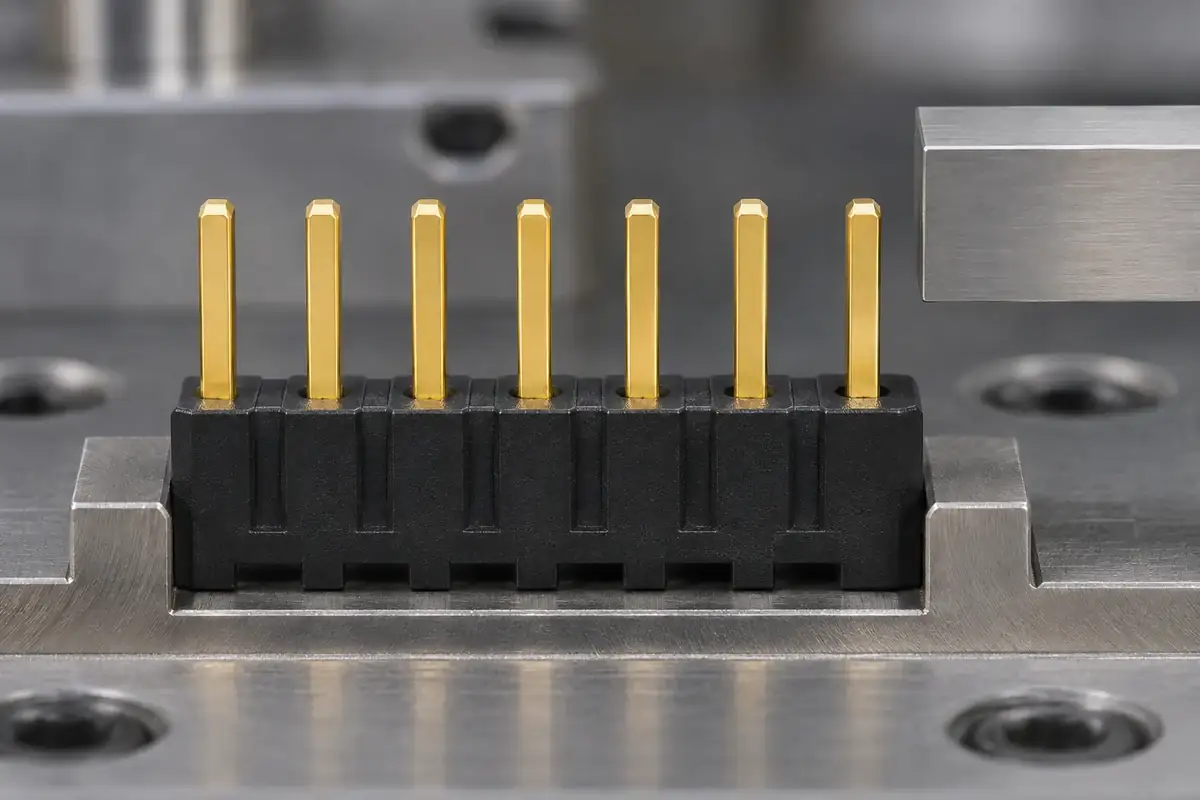
A tail projecting below the plastic is not necessarily the same length as the tail projecting below the circuit board. Board thickness and the distance between the base and board change the visible termination. A header that looks satisfactory as a loose component can therefore present a different soldering geometry when it is seated on the actual board.
Small stand-off feet often establish the gap under the base. Their height, contact condition and location should be part of the seating definition. If the assembly rests on an unintended gate vestige or trapped debris instead, the whole header may sit high even though every pin is correctly positioned within its insulator.
Separate a seating error from a pin-position error by measuring the plastic and the metal against independent references. If all pins are displaced with the body, investigate the board interface or installation fixture. If one pin differs while the base is seated correctly, investigate that contact's assembly and retention. The distinction prevents a board issue being compensated by changing the mold.
The discussion of header stand-off and soldering space develops the board-side constraints further. Here, the important point is to keep those constraints in the dimensional chain. Tail projection should be agreed with the board and joining process rather than chosen only to make the loose header match a sample photograph.
Find the stop that determines the final mating position
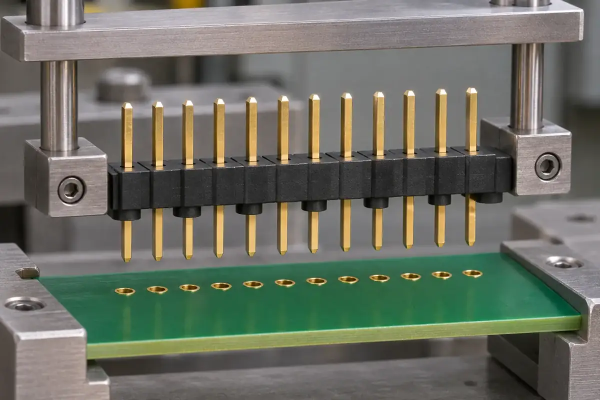
A socket can engage a pin over a range of positions, while a separate mechanical feature may determine where the boards finally stop. Identify that feature. It might be board hardware, a housing shoulder or another part of the equipment. If the stop is absent from the design review, an exposed-pin dimension can look adequate without defining the finished engagement.
Excessive projection is not automatically helpful. A longer pin can reach farther into a receptacle, but it can also approach an internal obstruction, extend beyond the intended contact region or become more vulnerable during handling. Evaluate both the shortest and longest permitted assemblies with the correct socket definition instead of maximizing the nominal exposed length.
Changing base height while leaving the pin and body seating unchanged can consume exposure on one side. Moving the body along the pin changes the division between the two sides. Changing total pin length introduces a third possibility. These actions can produce similar appearances from one view while having different consequences at the board termination and mating interface.
Use a section through the actual mating pair to keep those consequences visible. Show the seated plastic faces, the pin tip and relevant receptacle features, then relate them to the equipment stop. The aim is not to add dimensions everywhere; it is to establish a small set of dimensions whose references explain the completed assembly.
Control the dimension at the stage that creates it
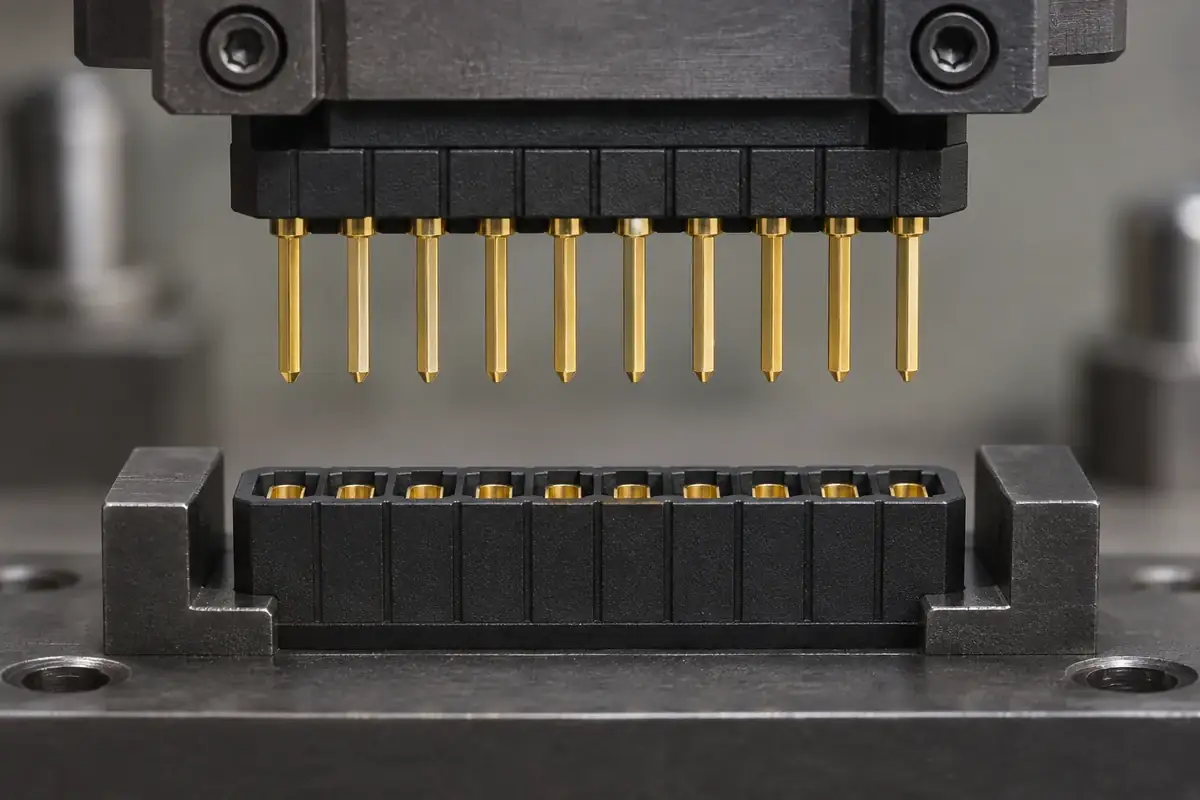
Inspect the bare molded base for the surfaces and hole features that establish contact position. Inspect the pins for their relevant geometry and condition. After insertion or molding around the contacts, inspect the resulting exposed lengths from the agreed references. Measuring only the incoming components misses variation introduced by the assembly operation.
The fixture should set the intended position without using a fragile pin tip as an accidental stop. Decide whether the process references a contact shoulder, a plastic face or a controlled tool position. That decision also determines which wear surfaces and setup conditions deserve attention when the measured lengths begin to drift.
When a header later appears to have changed height, compare it with its recorded assembled state. The article on an insulator sliding along its pins distinguishes a configured position from unintended movement. A difference between two approved variants is not evidence of drift, while a change within one identified assembly deserves investigation.
For custom header insulator bases, include the contact drawing, the intended body position, board thickness and mating counterpart with the plastic model. State the finished dimension and the stage at which it is accepted. This keeps the molding, contact supply and assembly discussions connected to the same geometry.