
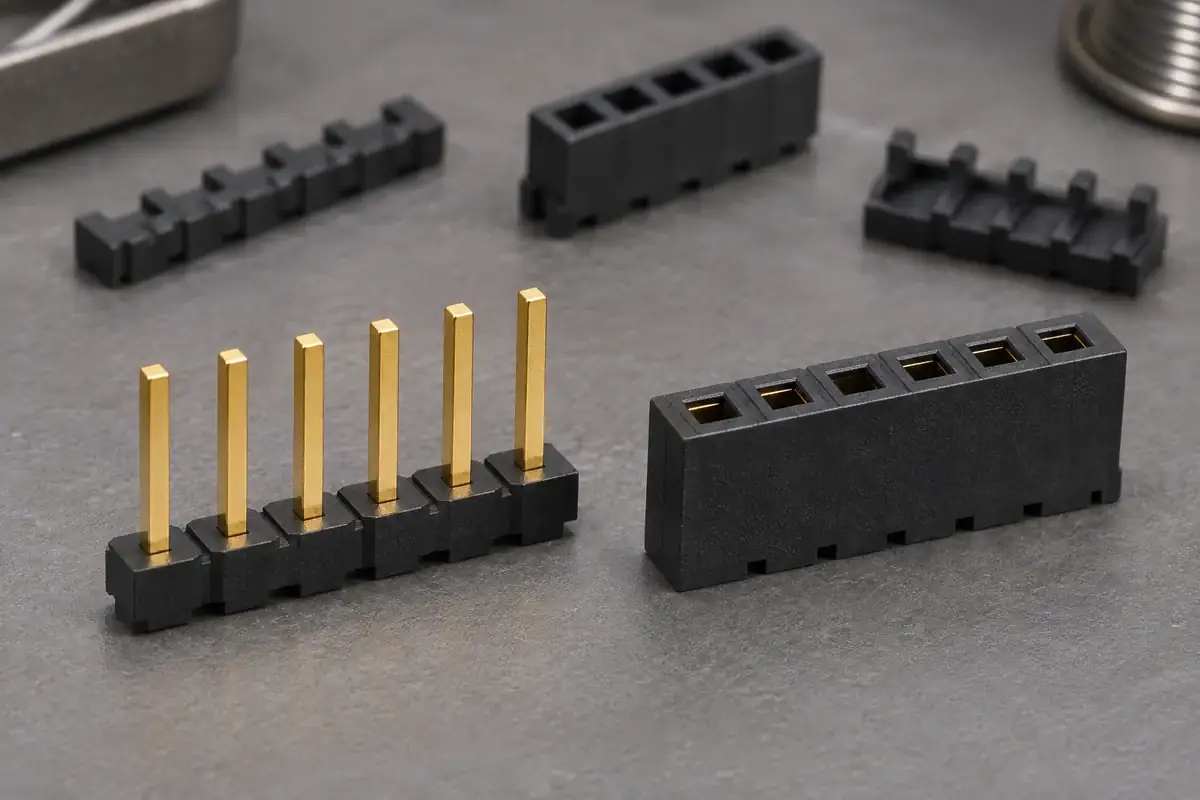
A pin header and its mating socket can have the same number of positions and still need quite different plastic parts. The header holds projecting metal posts in a defined pattern. The socket surrounds receptacle contacts that must admit those posts and maintain an intended contact relationship. Matching the outside width of the two plastic strips therefore tells you little about whether either design supports the connection correctly.
For a custom insulator, start with the metal contact and the assembly sequence. Identify what the plastic must locate, what it must retain and which movement must remain possible. This separates the job of a simple pin-support strip from that of a socket cavity, and gives the molding review a more useful starting point than the generic description connector housing.
Product design illustrations accompany the assembly and manufacturing explanations below.
The header base establishes a position for each pin
On a conventional unshrouded header, the molded strip establishes the relationship between adjacent posts and provides an insulating body around their supported region. The pin extends beyond that body toward a mating receptacle and often in the opposite direction toward the circuit board. Both projecting lengths matter, but they belong to different interfaces and should have separate drawing references.
The hole through the base is not simply an empty passage. Its entry, retention region and exit must suit the selected pin geometry and installation method. Depending on the construction, retention may rely on interference, a defined metal feature or molding around an insert. A drawing should identify the actual arrangement instead of assuming that every square pin is held by the same mechanism.
That distinction becomes practical during assembly. A lead-in can help a pin enter the base, while a local retention feature resists later axial movement. Enlarging the entire hole to make insertion easier may also reduce the engagement that keeps the finished pin at its intended height. Review those regions separately before changing a core dimension or the pin specification.
Samtec's TSW header family offers multiple terminal lengths and orientations within a header-strip system. This illustrates why the complete contact configuration belongs in the part definition. An insulator drawing needs the pin revision, its supported portion and its final position, rather than only a row count and a nominal grid.
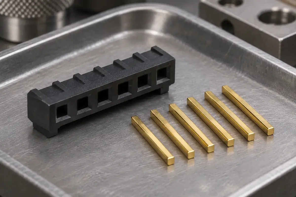
The socket insulator must accommodate a working contact
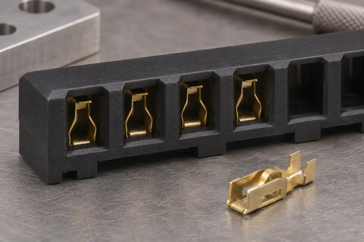
A receptacle contact usually has a receiving region that interacts with the mating pin. The plastic needs to position that contact while leaving the intended contact action available. A cavity that tightly traps a spring feature can change how the metal moves. A cavity that leaves the contact insufficiently retained can allow the entire terminal to shift instead of producing the expected mating action.
The entry opening and the contact's active region are related but are not interchangeable. The opening can guide an approaching pin toward the receptacle; it should not become an unintended hard stop or scrape against a correctly positioned post. Examine the pin envelope through the entry, including the allowed approach conditions, rather than judging the opening from a top-view photograph.
Samtec's SSW socket-strip information distinguishes contact options and termination configurations. The relevant lesson for a custom plastic base is that the metal receptacle remains part of the design definition. A housing cavity cannot independently establish the contact force, electrical performance or durability of an unspecified terminal.
Contact loading also changes the cavity design. A contact inserted from below may need an entry path and a stop that differ from a contact loaded from the mating face. Decide how the contact reaches its seated position and how that position is checked. Tool access, molding access and inspection access should then be reviewed against the same sequence.
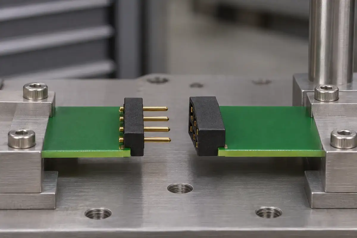
The two insulators meet through an assembled system
Correctly spaced pin tips do not establish a complete mating condition. The pin must enter the intended receptacle region to the required depth without reaching an unintended obstruction. Board spacing, connector seating and the plastic-body locations all contribute. Compare the assembled cross-section using the selected contact drawings, then identify which surfaces actually determine the final position.
For a pair of boards, mechanical supports can establish the board separation independently of the connector. If that support height conflicts with the connector's intended engagement, the assembly may appear securely fastened while the contacts are shallowly engaged or the plastic is being compressed. Treat the supports, connector bodies and contact lengths as a connected dimensional chain.
A bare header also exposes its pins during handling. A socket's taller cavity walls may protect its receptacles, but those walls need room for the mating approach. Protective features can improve handling while restricting access or increasing molding complexity. Decide which exposure the part must survive before adding walls simply to make the two halves look alike.
Electrical insulation requirements remain a separate design input. Plastic between neighboring contacts, external surfaces and the operating environment influence the relevant paths. The appearance of a tall wall alone does not establish an electrical rating. Agree the material evidence, geometry and completed-assembly evaluation required for the application, rather than assigning a rating to an illustration.
Make the molding request specific to the plastic component
For the header side, supply the pin model, retention feature, assembly direction and exposed-length references. For the socket side, supply the receptacle model, seating arrangement and space needed for its working portion. In both cases, identify surfaces where flash, gate vestige or ejection marks could interfere with contact loading or mating.
The inspection plan should follow those functions. Hole size, position and body height are useful only when measured from references that correspond to assembly. Our discussion of connector pitch and inspection datums explains why a visually regular row is not enough to establish its position relative to the rest of the part.
Keep the supply boundary equally clear. A request for a molded base differs from a request for a complete header with plated pins, or for a socket with installed contacts. Specify who supplies the metal components and reference samples, who performs assembly, and which records are needed before the component configuration can be approved.
For custom pin-header and socket insulator bases, send the plastic and contact drawings together with the intended assembly state. The related board-to-board housing overview can help when the design also needs shrouds or guiding features. Define those additional functions explicitly so that the mold and sample review follow the actual connection.