
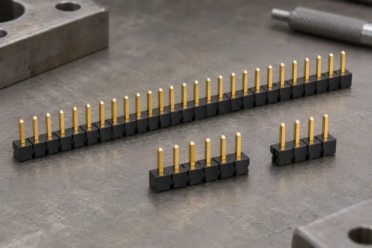
A long header strip separates at the intended position, but a fine crack continues toward the last pin. The contact count is correct and the section still fits the board, so the damage can be easy to overlook. Yet the end wall is part of the support around that contact; losing it is different from producing an acceptable cut surface between two positions.
The word breakaway does not define a universal cutting method. Some strips are supplied with separation features and a recommended tool, while other connector bodies are not intended to be divided at all. Start with the selected product's instructions. For a custom molded strip, define the separation operation as part of the design rather than leaving it to an improvised final step.
Product design illustrations accompany the assembly and manufacturing explanations below.
Check whether the chosen strip and tool belong together
Harwin's M20-9990645 product information identifies that header as cuttable and points to a specific cutting tool. This is a useful example of a defined product-and-process combination. It does not establish that an arbitrary strip of similar pitch can be snapped or cut using the same method.
Before investigating a crack, record the strip revision, the intended cut position and the tool actually used. Also note whether the section was separated before pin insertion, after contact assembly or after soldering to a board. The surrounding constraints differ, and a method that relies on supporting a loose strip may be unsuitable once it is attached to another component.
Distinguish a cutting operation from a bending or snapping operation. A blade removes or displaces material along a defined path, while bending loads the remaining bridge and neighboring walls. The resulting fracture surface can look similar at a glance, but the loads reaching the end contact may differ. Use the method agreed for the actual design.
Do not use the metal pins as convenient levers for dividing the strip. That can introduce contact displacement or bend a post even if the plastic separates cleanly. Support and act on the intended part of the assembly. The condition of the contacts after separation belongs in the acceptance review alongside the appearance of the molded end.
Follow the notch toward the nearest contact opening
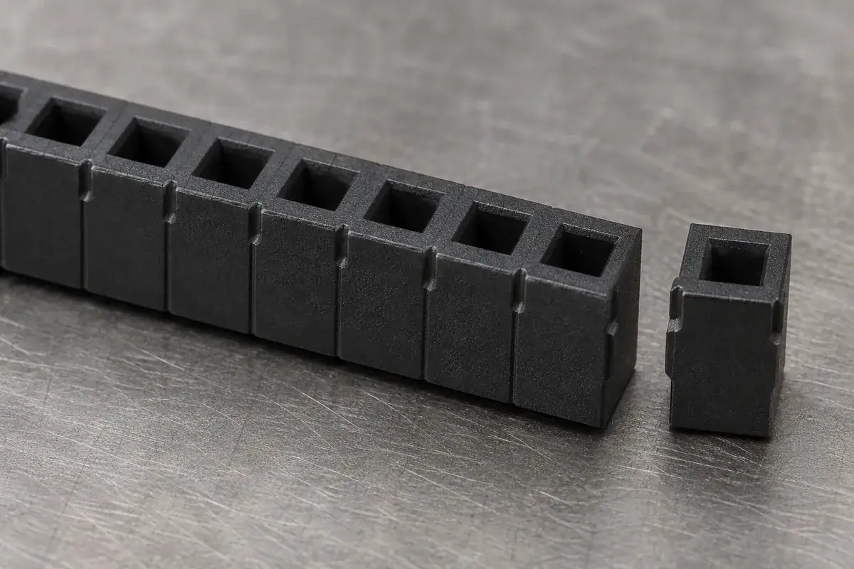
A separation notch reduces the material that must be divided, but it also changes the local section around adjacent positions. Examine the shortest path from the notch root to the contact opening. If the intended separation path competes with a thinner wall toward the bore, the resulting damage may extend into a functional region instead of remaining between positions.
The remaining end-wall thickness deserves its own definition. A strip can have ample material around interior contacts while leaving the last contact poorly supported after division. Review the finished short section, including the shortest permitted length, rather than judging only the continuous molded strip before cutting.
Parting lines, local molding features and contact retention geometry may meet near that same end wall. A small retention shoulder can load the plastic precisely where the separation operation has reduced its support. Look at the contact and molded section together. An acceptable empty-base cut does not automatically establish the condition after the pins are installed.
A sharper notch can concentrate the separation action, while a larger residual bridge can improve handling strength before the cut. Neither direction is universally better. Compare transport, feeding, contact loading and the chosen cutting operation so that the strip survives earlier handling and separates in the intended region at the designated stage.
Look at the support immediately beside the cut
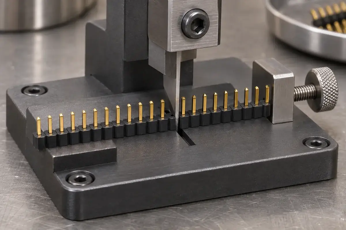
A cutting tool needs more than a sharp edge. The strip must be located so that the blade reaches the intended separation region, and the retained section needs support against the reaction. If the body can twist or lift, the operation may bend the last contact position before the plastic is divided.
Harwin's Z1022-00 tool description includes an adjustable stop for placing compatible headers on its gauge plate. The general design-review point is repeatable location. For a custom fixture, agree the reference that sets the cut position and check that the stop does not push on a flexible pin or an inconsistent broken end.
Compare the first and last pieces produced from a strip, because their available support can differ. A long remaining strip is easy to locate, while the final short section may be difficult to hold close to the cut. Tool access should be checked for all required section lengths rather than only for the most convenient sample.
Blade wear, clearance and debris can change the operation over time. Inspect the supported region and cut face when the damage pattern changes. A recurring crack at one end may be related to location or support, while variation across a batch may require a broader review of material, molding condition and tool condition. The pattern guides the next observation; it is not a diagnosis by itself.
Accept the finished section, not just the contact count
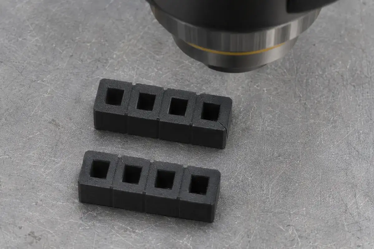
Define an acceptable separated end using the functional geometry. The inspection should distinguish an intended cut surface, loose debris, a displaced contact and a crack reaching the retained pin region. A photograph approved only for general appearance may not show whether the remaining wall still supports the contact as required.
Check pin position after separation from the same references used for the finished part. Cutting can introduce a local tilt that is difficult to see in the continuous strip. The guide to pin pitch and inspection datums helps connect that check to the mating pattern instead of measuring each tip from an arbitrary edge.
Consider supplying molded-to-length sections when the required quantities and variants justify it. That can remove a separation operation but changes the tooling and inventory discussion. Retaining a longer cuttable strip can offer flexibility, provided the end condition and cutting method are controlled. Compare the actual mix of section lengths and handling steps before choosing either route.
For custom pin-header insulator bases, include the finished section lengths, separation locations and contact-loading sequence in the tooling review. If cutting has already damaged samples, provide views before and after the operation and the actual support arrangement. The related pin retention discussion can help when end damage is accompanied by contact movement.