
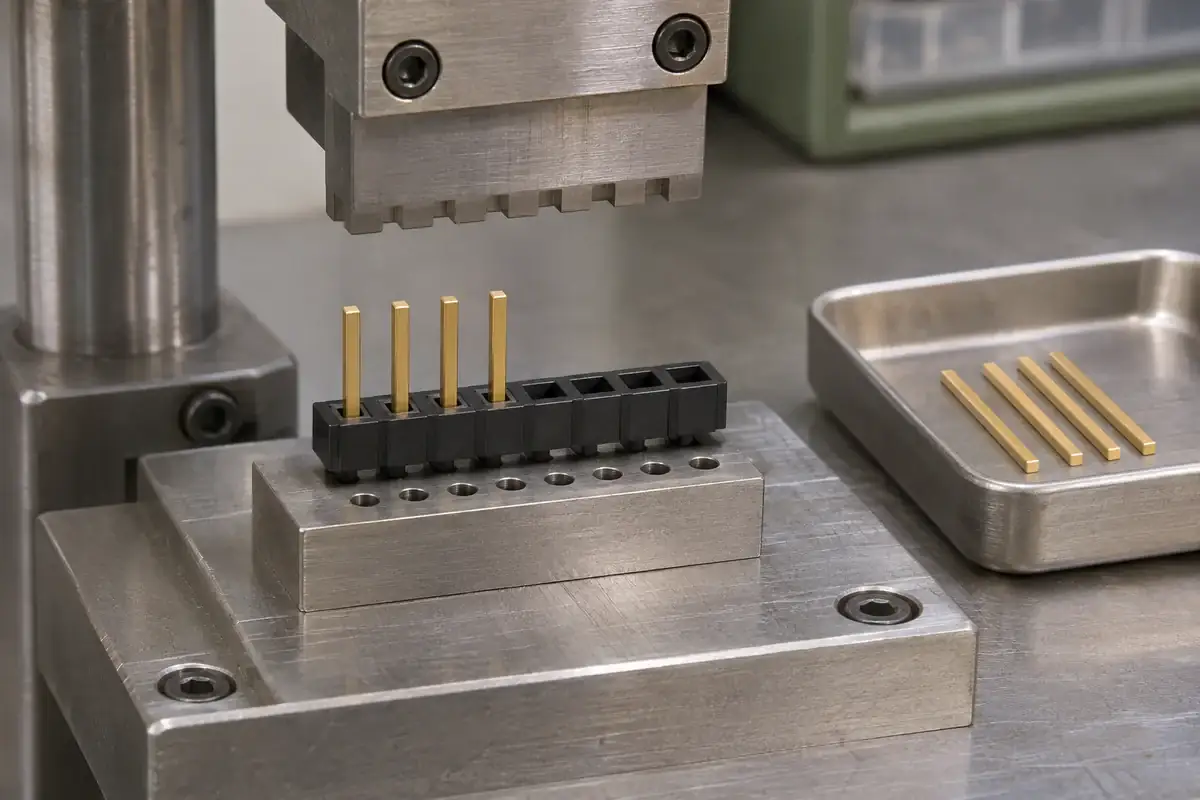
A press can deliver a repeatable stroke while the plastic base beneath it bends differently on every cycle. The finished pins may look evenly spaced, yet the strip can acquire a bowed underside, stressed hole edges or inconsistent seating. Repeatable machine motion becomes useful only when the component has a repeatable way to react to the insertion load.
Start by naming the operation. Installing a metal post into a molded insulator is different from inserting a completed press-fit connector into plated PCB holes. The retained interface, support surfaces and acceptance method are different. Instructions for a PCB press-fit product should not be borrowed as force or tooling requirements for a custom plastic-base assembly.
Product design illustrations accompany the assembly and manufacturing explanations below.
Draw the load path before designing the nest
Follow the force from the punch into the contact, through the retaining interface and into the plastic. Then identify where the plastic transfers it to the fixture. A nest that touches only the outside ends of a long strip can leave the insertion region unsupported. A closely fitting pocket is not automatically a supporting pocket if its floor never reaches the intended bearing face.
The receiving surface should support the geometry intended to carry the load while allowing the contact tail to pass freely. If the tail bottoms against the fixture before the pin seats, additional press travel can bend the post or drive the base away from its reference. Tail clearance therefore belongs to the stroke review as well as the fixture drawing.
A support rail can be useful for a narrow strip, whereas a more complex base may need several defined bearing areas. Avoid resting the part on gate vestiges, ejector marks or small decorative ribs unless those features were deliberately specified as locating surfaces. Their variation can otherwise change the local support each time a part is loaded.
The same principle applies to the punch. The metal contact needs an appropriate driven surface and guidance, and the tool must avoid damaging its mating region or plated finish. Do not assume that the most accessible pin end is an acceptable press surface. Resolve the contact-handling method with the contact supplier and the intended assembly process.
Support the base without trapping it
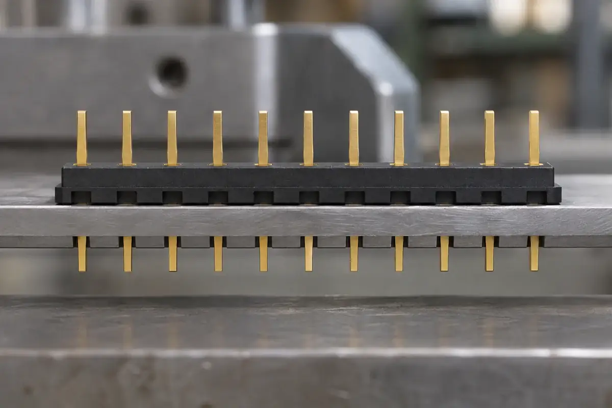
A nest needs enough locating control to present each hole to its pin, but it also needs a realistic loading and unloading path. A tight pocket around every outer wall can bind on permitted molding variation or hold a stressed part in an apparently straight condition. Once released, the strip may spring away from the position observed in the fixture.
Separate location from support where practical. A small number of defined references can locate the part, while broader lands react the axial load. Review the release direction and the surfaces that might drag against the part. Sharp tooling corners near thin molded edges deserve particular attention because a small loading misalignment can create a visible chip before insertion begins.
Consider the whole component family. A nest developed around a short header may provide inadequate support when the same approach is extended to a longer row. Conversely, a common long fixture can leave the end of a short part over a clearance pocket. Identify the supported positions for each approved variant rather than assuming that shared pitch makes the tooling interchangeable.
Pin loading sequence changes the problem too. When contacts are installed individually, previously fitted pins must clear the tooling during every subsequent step. When several are inserted together, one misaligned contact can load the strip unevenly. The setup should allow the cause of an abnormal operation to be isolated without forcing the remaining pins through.
Use seating and force information for different questions
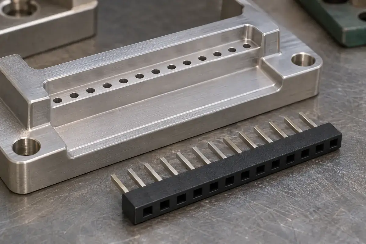
A stroke limit tells the machine where it stopped, not necessarily where the contact stopped relative to the base. Tool compliance, part seating and contact length all contribute to the relationship. Define the final contact position against the plastic reference that matters to the assembly, then determine how the process will establish and verify it.
Insertion force and contact retention are related to the interface but are not the same acceptance result. The TE PTL header specification, for example, defines a retention evaluation with the housing secured and load applied opposite the insertion direction. Its numerical limits belong to that product; the distinction between installing a contact and testing its retention is the useful lesson for a custom development.
If force-displacement information is used, connect the expected trace to the physical stages of your operation. Initial guidance, entry into a retaining region and arrival at a stop can produce different features. A single peak value may hide a premature collision followed by plastic yielding. Establish limits from the approved component and process evaluation, not from an unrelated header.
After unloading, inspect the base and pin position in a free condition as well as in the fixture. A support can temporarily mask bow or hold a displaced pin upright. Review the surfaces near the loaded hole, the underside bearing lands and the exposed contact ends. A successful cycle requires the accepted part geometry to remain after the tooling is removed.
Design the molded part and its tooling together
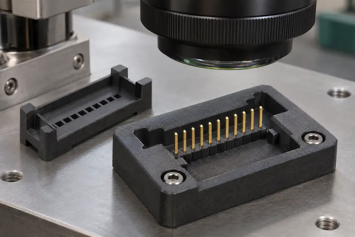
Where the base offers no suitable reaction face, a controlled support feature may be a better solution than a complicated nest trying to catch a fragile edge. That feature must fit the available envelope and avoid blocking soldering, cleaning or the mating component. Changes should be considered against the full assembly rather than added solely for manufacturing convenience.
Keep the assembly tool revision linked to the contact and base revisions. A change to exposed tail length can require deeper clearance, while a changed underside feature can alter seating even when the overall base height is unchanged. Documenting these relationships makes it easier to assess a variant without repeating a failure that appears unrelated to the drawing change.
Our custom insulator-base review starts with the metal interface, plastic geometry and installation method. Send those definitions together with the intended tooling and sample scope. For parts that include formed contacts, also review the bending and base-installation sequence, since it changes which surfaces remain accessible to support.