
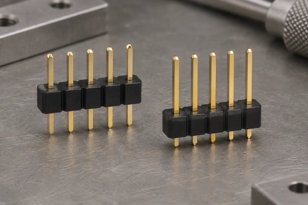
A header arrives with the plastic strip at one height, then appears lower on the pins after board installation. It is tempting to call the plastic loose and tighten every hole. Before changing the tooling, establish whether the body actually moved, whether the two parts are the same configured variant, and which operation first changed the observed position.
Some header systems are manufactured with different body positions to achieve different stack heights. That intentional configuration is different from movement during handling, soldering or mating. The investigation should begin with an identified part and a measured reference state. Otherwise, a comparison between two legitimate variants can be mistaken for a retention failure.
Product design illustrations accompany the assembly and manufacturing explanations below.
Distinguish the specified position from unintended movement
The Samtec DW series explicitly allows manufacturer-configured body positions along a terminal. The useful distinction is who sets the position, how it is controlled and what condition is supplied. A configurable product does not establish that a customer may push the plastic to any convenient height after delivery.
Compare the drawing revision and full component designation before comparing samples. Check the mating-side exposure, board-side exposure and plastic-body height from the same references. If the difference is already present before either sample enters the assembly process, investigate configuration and incoming supply before looking for an operation that supposedly caused movement.
If movement is confirmed, record whether the whole body shifted relative to all pins or whether individual pins moved by different amounts. A uniform change may point toward a process loading the body against an aligned row. A single displaced contact suggests a more local interface or assembly issue. These observations narrow the investigation without proving the cause on their own.
Also inspect for a false visual reference. A tilted base, a high stand-off pad or an uneven board can make the pin tips appear to have changed height. The guide to exposed pin length explains the relevant dimensional chain. Establish movement between metal and plastic directly, rather than inferring it only from the distance to the board.
Inspect the interface that is supposed to resist sliding
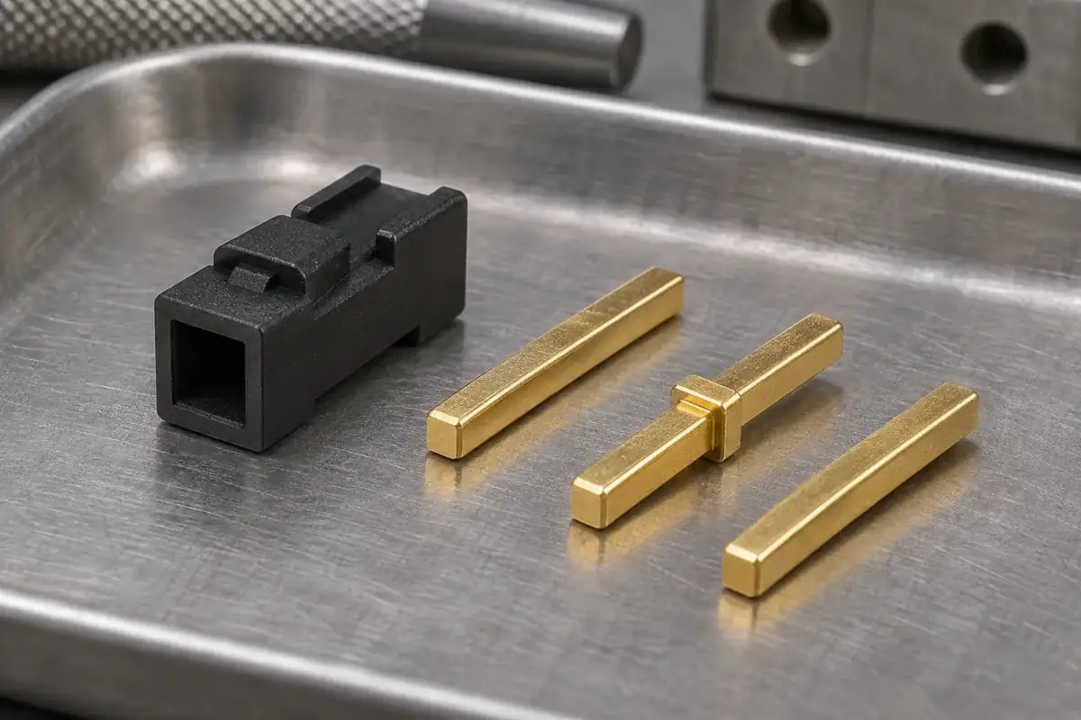
First identify the retention mechanism. A pressed-in post, a contact with a defined shoulder and an insert-molded pin do not resist movement in the same way. The relevant drawing should show where load is transferred into the plastic and which direction is restrained. An unspecified square hole leaves too much of that function to assumption.
For an interference-based arrangement, review the contact cross-section and the molded hole along the engaged length. Entry chamfers, taper, local reliefs and the pin's corner condition can change the effective contact region. Measuring only the mouth of the hole can miss a loose region deeper in the base or a short interference band carrying most of the load.
Increasing interference can increase insertion demand and local stress. It can also make orientation or fixture alignment more sensitive. Before reducing a hole dimension, examine whether the existing process can support the base and guide the pin through the proposed engagement. A retention improvement that cracks the end positions during insertion is not a satisfactory component solution.
Where a metal shoulder or other feature is intended to resist withdrawal, confirm that it reaches the required location. A partially installed contact can have the correct-looking exposed length from one face while missing the intended engagement region. Review the finished contact position together with the feature that actually opposes movement.
Find the process step that applies the displacement load
Check the component after the operations that can load it: unpacking, fixture placement, pin insertion, board placement, joining and mating. The purpose is to locate the first change in an identified sample. A final inspection after several operations can show that movement occurred while leaving the mechanism and timing uncertain.
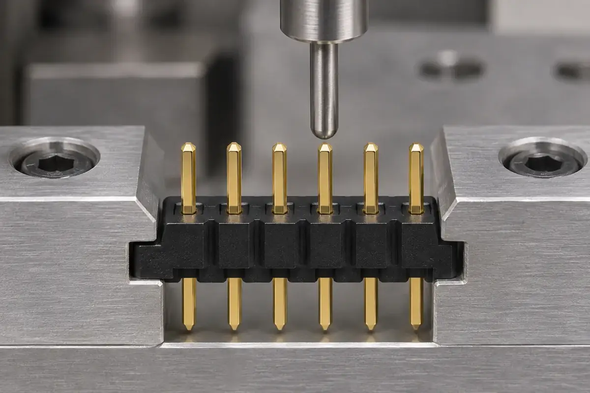
During board insertion, the pin tails may meet resistance before the plastic reaches its intended seating surface. If a tool continues pushing on the body while the tails are obstructed, the retention interface sees the resulting load. Investigate hole alignment, the entering contact condition and the force application point before deciding that the plastic should simply grip harder.
Temperature and time can also affect a polymer-loaded interface. The relevant question is whether the actual resin, retention geometry and process exposure maintain the required position under the specified conditions. Do not borrow a soldering allowance or retention value from a different header family. Evaluate the component configuration in the process for which it is intended.
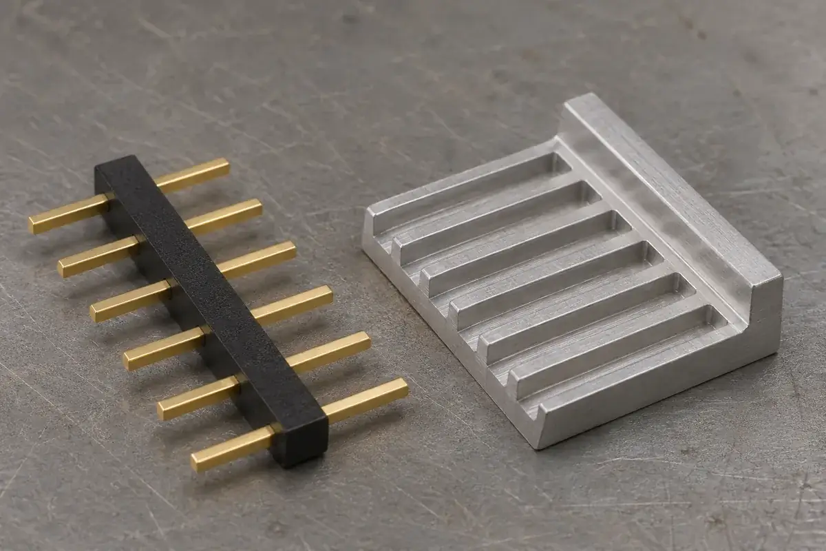
Handling features deserve a similar review. A tray pocket that supports pin tips while a cover pushes on the insulator can create a load that was absent during the component check. Packaging and transfer fixtures should support the assembly through intended surfaces, leaving vulnerable ends clear where needed. Repeated movement caused by the tray should not be compensated by an unexplained molding adjustment.
Choose a correction that addresses the observed mechanism
If the issue is incomplete insertion, improve the definition and verification of the seated state. If the body is being displaced by an obstructed board insertion, resolve that interference and support path. If the retention geometry is insufficient in the required condition, revise the contact and plastic interface together. These are different corrective actions even when the visible symptom is a changed pin height.
A retention evaluation should state the support arrangement, direction of loading, component condition and acceptance criterion. Otherwise, two fixtures can generate different readings because one grips the pin while the other bends it or compresses the plastic. Record the displacement as well as the applied condition so that a small initial seating movement is not confused with continued sliding.
Inspect the part after evaluation for cracks, scoring and permanent changes at the interface. A higher measured resistance obtained by damaging the plastic is different from stable retention in an intact component. The separate article on pin insertion fixture support explains how the assembly reaction can be directed toward more suitable plastic surfaces.
For custom molded header bases, provide the original and changed positions, the relevant contact drawing and the operation where movement first appears. Include the actual resin and component revisions. That evidence supports a focused review of retention, assembly and exposure instead of an open-ended request to make the strip tighter.