
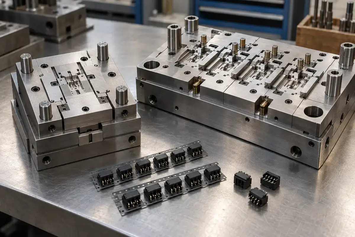
A small set of connector samples can answer whether the concept fits, yet leave the production process largely untested. The samples may use individually placed contacts, a generous loading nest or a simplified cavity arrangement. Those choices can be sensible during development. Trouble begins when their results are treated as proof that a different production route will behave identically.
The transition should preserve the important conditions and deliberately re-evaluate the ones that change. That requires more than replacing a soft tool with harder steel or increasing the number of cavities. For insert-molded connector components, the incoming terminal, its support, the polymer flow and the release sequence form one manufacturing system.
Product design illustrations accompany the assembly and manufacturing explanations below.
Match each sample route to the question it can answer
A printed or machined housing with separately installed contacts can help evaluate envelope, access and some assembly relationships. It does not reproduce the polymer flow around an insert or the retention created by the intended molding geometry. Keep those early units useful by stating what they represent, rather than asking them to validate a manufacturing mechanism they do not contain.
A development insert-mold tool moves the investigation closer to the intended process when it uses the planned resin and representative terminals. Even then, a loose insert placed into a single cavity may differ from a carrier strip indexed through a production tool. The sample is evidence for its own route; the transfer review identifies which findings can reasonably carry forward.
The article on insert molding versus contact assembly explains that route distinction in more detail. Choosing a sample route is therefore a decision about what uncertainty to remove next. A quick fit model and a process-representative molded sample can both be valuable, provided their roles are not confused.
Transfer the restraint, not just the cavity outline
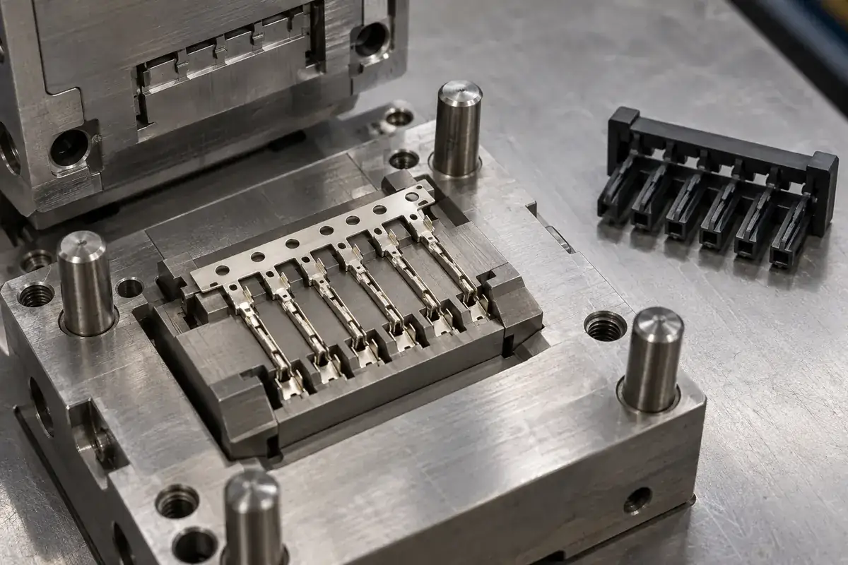
When production adopts a different carrier or feeding arrangement, compare the locating and support conditions explicitly. A terminal that was supported close to the molded region in the development nest may have a longer free span in the production tool. The outer plastic CAD can remain unchanged while the metal experiences a materially different loading condition.
Molex's insert-mold tooling discussion describes loading elements that position contacts and other components. Its examples concern cable and connector tooling, and the detailed route varies by product. The relevant principle is that the insert-positioning hardware belongs in the tool design review, not merely in an instruction attached after the cavity is finished.
Compare incoming terminal revisions as carefully as polymer geometry. A stamped production terminal may differ from an early machined approximation in edge condition, forming history, plating or carrier connections. Those differences can affect loading, protected surfaces and retention. Identify which attributes the early sample reproduced and which need confirmation with the production terminal.
Automation adds a transfer motion that a careful manual trial may not expose. Review orientation, seating, carrier guidance and release from the handling device. An insert must arrive correctly and remain correctly located when the mold closes. A successful robot placement in an open tool is only one part of that sequence.
More cavities create more conditions to compare
A multi-cavity layout introduces a distribution problem. Different positions may see different flow paths, thermal conditions or loading access. Do not assume that a satisfactory part from one cavity demonstrates every other position. Plan observations that retain cavity identity and examine the functional terminal and polymer features relevant to the component.
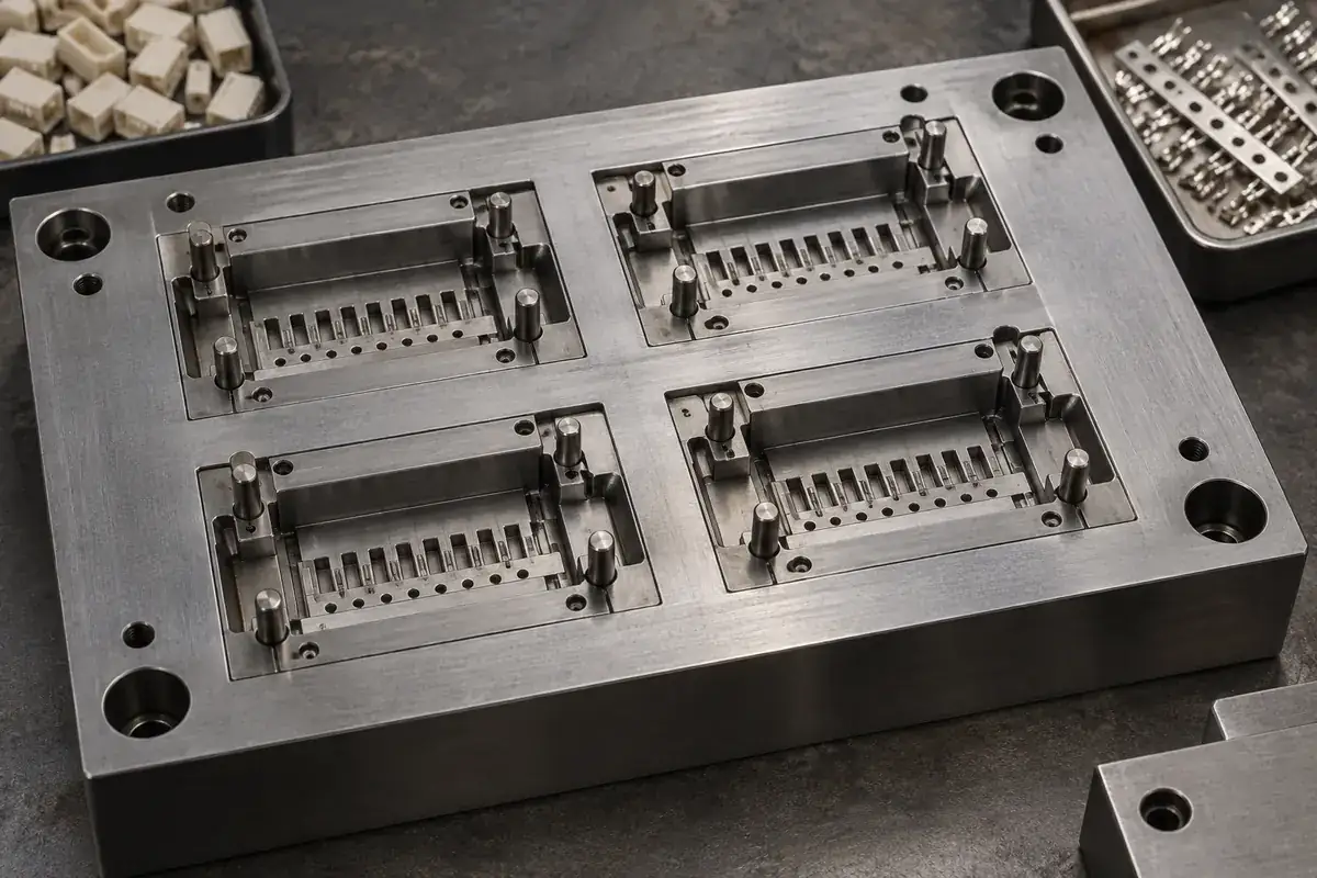
Changing the runner or gate can also change local orientation and shrinkage. The finished outline may remain nominally the same while the released terminal row responds differently. Compare the intended production filling arrangement before freezing the tool. The guide to terminal shift during molding describes why insert support and local melt loading should be reviewed together.
Tool material and construction must suit the chosen resin, geometry and service plan. A simple distinction between prototype aluminum and production steel does not settle thin shutoff durability, thermal control or maintenance access. Ask which features are replaceable and how their condition can be checked without repeatedly rebuilding the whole mold.
A planned replaceable insert can make later corrections more manageable, but modularity also adds interfaces that must locate repeatably. Decide where replacement is useful and what establishes its position. The practical benefit comes from a controlled tool arrangement with accessible wear features, not from the mere presence of more interchangeable pieces.
Validate the complete release route
A production trial should include the operations that create the delivered component: molding, ejection, carrier cutoff, any approved secondary operation and packaging. A strip that looks satisfactory while still restrained in the tool may behave differently after release. Skipping those downstream steps postpones a key part of the dimensional review until production is already expected to run.
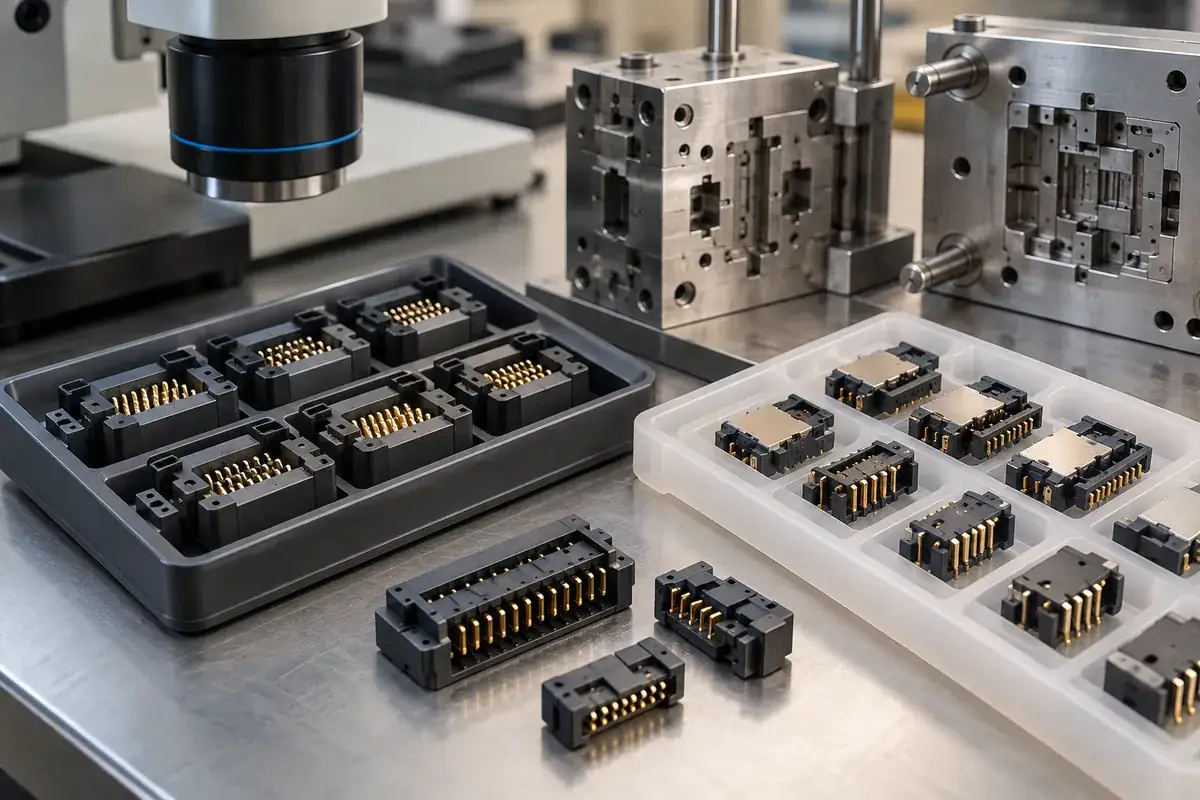
Define what constitutes a representative run for the project instead of choosing a universal sample count. The evidence should address the expected variation in cavity position, insert supply and relevant operating conditions. Keep development exceptions visible, including hand sorting, special loading assistance or adjustments that would not be available during the proposed routine process.
Measurement methods should transfer with the component. If development used an optical setup and production introduces a functional fixture, compare what each method detects and what it can conceal. A fixture that constrains terminals into position may be helpful for assembly verification but unsuitable for revealing their unconstrained location. The drawing and functional requirement should determine the intended condition.
For custom insert-molded connector components, a useful production review ends with the changed conditions identified and evaluated. Our insert molding service overview explains the broader process. The aim is to carry verified learning forward while testing the new loading, molding and release conditions that production introduces.