
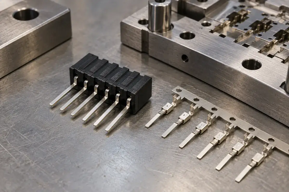
A row of terminals can enter a mold straight and leave it with a position problem, even when the plastic outline looks acceptable. The natural response is to change injection speed. That may help, but it can also hide a loading error, a weak support condition or movement that actually occurs after molding. The useful question is when the terminal first leaves its intended position.
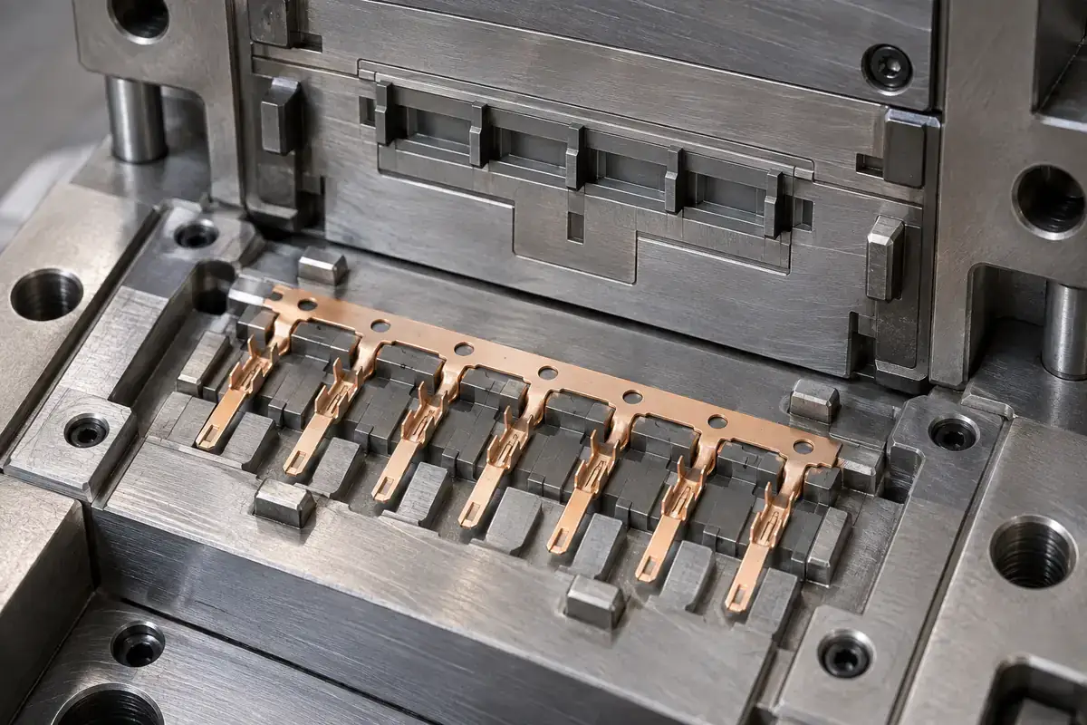
Think of the terminal as a slender metal member with specific restraints. Its carrier rail may locate one end, a tool land may support another region, and a free span may cross the area being filled. The plastic flow meets that arrangement, rather than an infinitely rigid CAD model. Reviewing the support and the filling sequence together makes a trial more informative.
Product design illustrations accompany the assembly and manufacturing explanations below.
Separate incoming position from movement during filling
Begin with the unloaded leadframe or individual insert. Check its condition in a repeatable reference setup before it is placed in the mold. A bent tail or a strip that rocks on its pilot features should not be recorded as molding-induced shift. Keep the carrier condition, terminal forming operation and handling route visible in the investigation instead of examining only the finished polymer body.
Next, inspect the loaded condition with the tool open and, where practical, confirm the seating after closure using a suitable setup method. A terminal can look properly located from above while sitting on debris or bridging a support. Closing the mold may then bend it before any resin arrives. This is a different failure mechanism from a terminal displaced by flowing melt.
The related discussion of leadframe carrier location concerns how the strip establishes position. Here the focus is what happens to the unsupported metal after that position is established. A useful trial record therefore distinguishes incoming, loaded, molded and released states, with the same terminal locations identified at each stage.
Review the load path through the terminal
Plastic reaches different surfaces at different times. If pressure acts on one side of a thin insert while the opposite side is not equally supported or loaded, the resulting force can bend or rotate the insert. The exposed area, the distance to its support and the local metal stiffness all matter. The machine pressure setting alone does not describe that local condition.
Autodesk explains pressure-driven deformation in its core-shift simulation documentation. That source concerns mold cores; applying the same load-path reasoning to a connector terminal is an engineering analogy, not proof that a particular terminal will move. A terminal assessment must use the actual insert geometry, material and restraints.
Consider a hypothetical flat contact with a long exposed span between its carrier and the molded crossbar. Moving a support closer to the loaded region may reduce bending, but it may also create a tooling contact mark or obstruct a surface intended to receive resin. Shortening the span is therefore a coordinated product-and-tooling decision, not a support added wherever space appears available.
Support on the wrong surface creates a different problem. The mating contact zone may need its geometry and plating preserved, while another region is intended for molding retention. Define which metal surfaces may touch steel, which may be clamped and which must remain clear. A stronger fixture is not automatically a better fixture if it damages the functional end of the terminal.
Use flow changes to answer a specific question
A gate near a terminal row can direct an early flow front toward exposed metal. Moving the gate may change that loading, but it can also change weld locations, fill balance and the amount of material needed to reach thin insulating walls. Treat gate position as part of a complete filling strategy rather than a stand-alone cure for bent terminals.
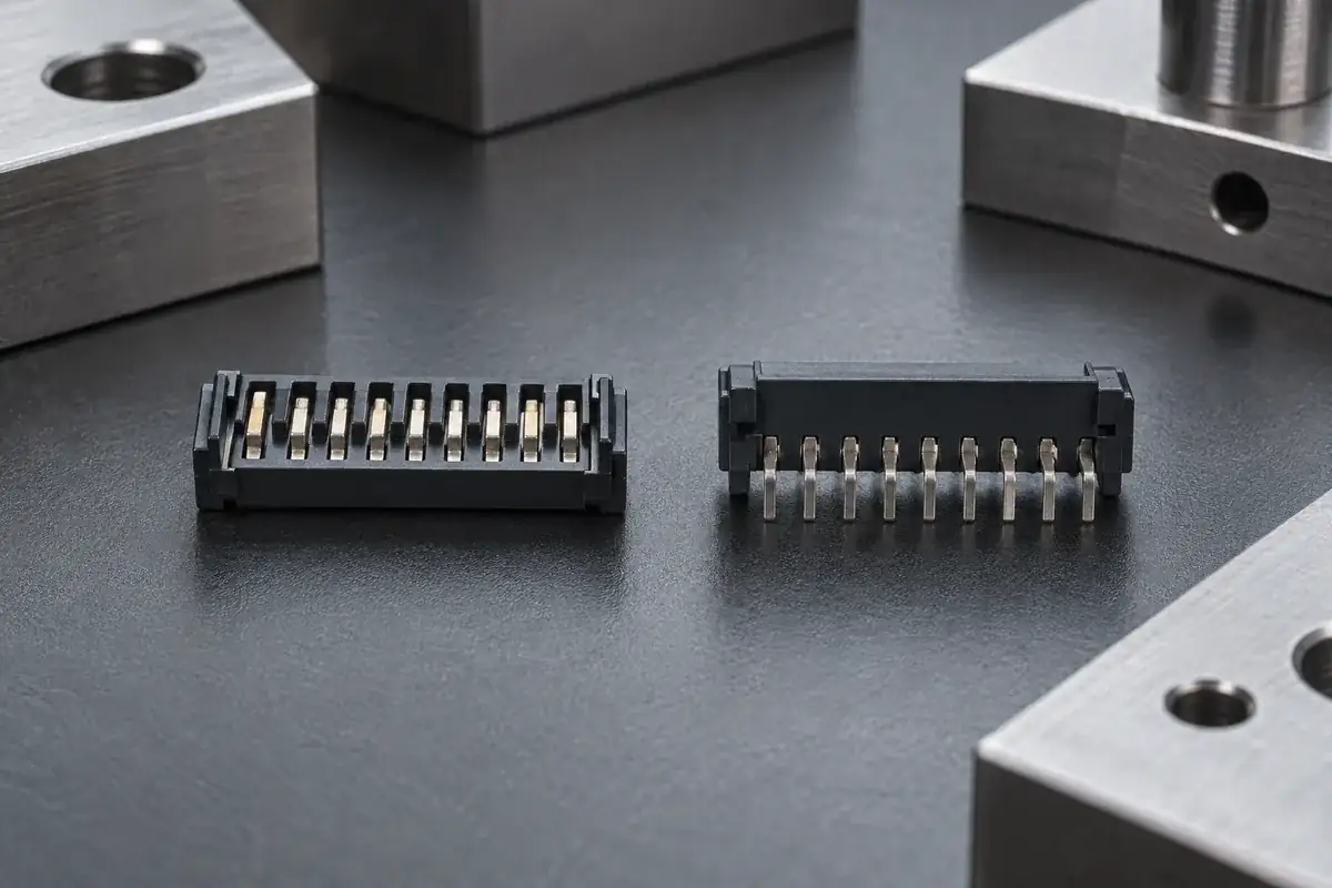
Reducing speed without a hypothesis can trade one defect for another. If the thin wall becomes harder to fill, the resulting trial may introduce short shots or a different pressure history. A more useful comparison holds the insert and its support constant, changes a justified part of the profile, and examines both terminal position and the completeness of the insulating geometry.
Simulation is most useful when its restraints resemble the tool. Declaring the whole terminal fixed will remove the movement the study is supposed to investigate. Conversely, leaving a locating region completely free can overstate it. Ask the analyst which contacts, clamping regions and material assumptions are represented, and use the result to choose a physical trial rather than call it a finished-part measurement.
The article on thin-wall filling and venting explains another part of this balance. Air evacuation, flow restrictions and terminal support cannot always be optimized independently. A tool change should be reviewed against the protected contact surfaces and insulating features as well as the visible direction of terminal movement.
Check what happens after the cavity is filled
Not every position change belongs to the filling stage. Ejection, cooling outside the tool, carrier trimming and transfer into packaging can alter the released component. If a module is acceptable while attached to its rail but moves after cutoff, changing injection speed alone is unlikely to identify the full cause. Preserve samples from the intermediate states rather than inspecting only the final tray.
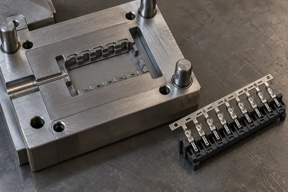
Measurement should also avoid straightening the part unintentionally. A tightly constrained nest may force a terminal row back into alignment and make two different conditions appear equal. Use the intended drawing references and identify whether the measurement is taken freely supported, assembled or constrained. The pin-pitch and datum inspection guide explains how those references connect the terminal pattern to its mating interface. Record the support condition alongside the result so later trials can be compared fairly.
For a new insert-molded connector component, bring the terminal drawing, carrier details and protected surfaces into the early tool review. Our insert molding service connects those details with the molding route. The practical objective is a repeatable position through loading, molding and release, supported by observations at each stage.