
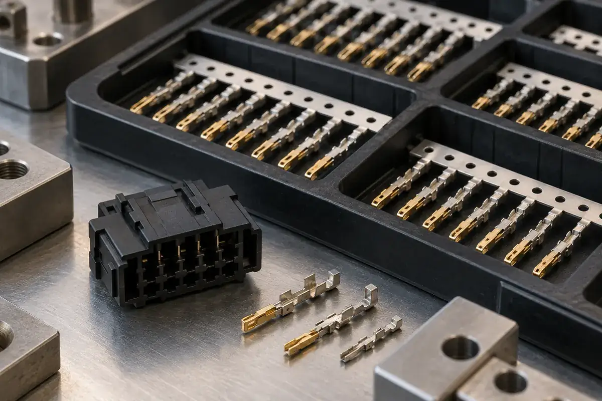
A plated terminal is already a functional component when it reaches the molding operation. Its finish is not simply a decorative coating added to make the finished connector look clean. Contact tips, solder tails and the region captured by plastic can have different requirements. Protecting all three starts with identifying them before a loading fixture or handling tray is designed.
The most obvious damage is a bent contact, but surface problems can be less conspicuous. A mark from a tool, contamination transferred from packaging, or residue deposited near the mating zone may survive molding without affecting the plastic's appearance. A visual review of the housing alone therefore cannot establish that the insert has passed through the process unchanged.
Product design illustrations accompany the assembly and manufacturing explanations below.
Keep the finish map connected to the contact function
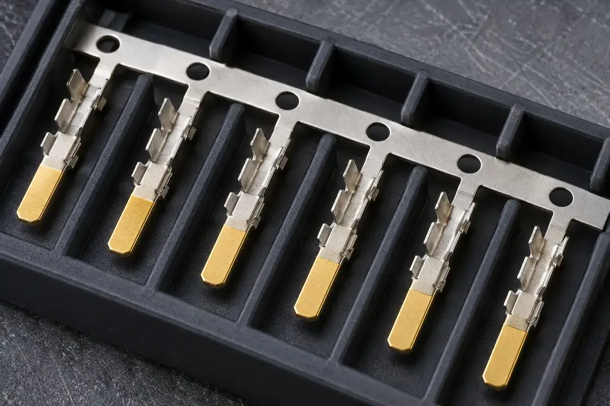
Selective plating means that different areas of the same terminal can intentionally carry different finishes. Samtec's contact and terminal design guidance describes the use of gold in contact areas and tin on tails in relevant connector designs. That is useful context, but the actual finish and coverage boundaries must come from the terminal's own controlled specification.
Do not infer plating thickness, base metal or contact capability from color. Gold-colored material in an illustration does not establish a plating system, and a silver-colored tail does not identify a particular deposit. The molding team needs the terminal drawing and finish requirements, including any areas where clamping, sliding contact with tooling or cosmetic marks are restricted.
For a hypothetical terminal strip with a contact tip at one end and a carrier rail at the other, the rail is usually the more practical handling candidate. Even then, confirm that gripping the rail cannot twist the narrow connections leading to the contacts. Protecting the finish while bending the terminal would solve only half the problem.
Design handling around permitted touch points
Map every transfer from incoming packaging to the mold and then to the finished-part container. Each transfer has a support point, a gripping point and a possible sliding path. A component that is secure in one orientation may brush its mating tips against a tray wall when turned over. Looking at the complete route reveals contact events that an isolated fixture review misses.
Dedicated pockets can separate adjacent terminals and keep their functional surfaces off the container floor. Their shape still needs to allow removal without dragging a tip across an edge. A tightly packed tray may look efficient while making careful extraction difficult. Evaluate the release motion as well as the storage position, particularly for thin formed contacts that can snag each other.
Samtec's handling and storage guidance includes contamination precautions for its products. For a custom insert, agree equivalent controls with the contact supplier rather than copying a universal storage life. Packaging materials, cleanliness expectations and exposure history should match the specified finish and the next manufacturing operation.
Loading equipment should reference approved features instead of relying on a delicate mating surface to correct alignment. If the nest needs to slide a contact into place, ask what surface performs that sliding and what condition is acceptable afterward. The answer may be a revised carrier feature, a different loading direction or a tool change rather than additional operator care.
Separate molding protection from cosmetic cleanup
Insert molding brings heat, pressure and close contact with tooling into the handling route. These conditions should be reviewed with the terminal and plating specifications, particularly where a finish transition lies near the polymer boundary. Qualification should use the intended terminal source and finish condition; an unplated development strip cannot answer every question about the plated production component.
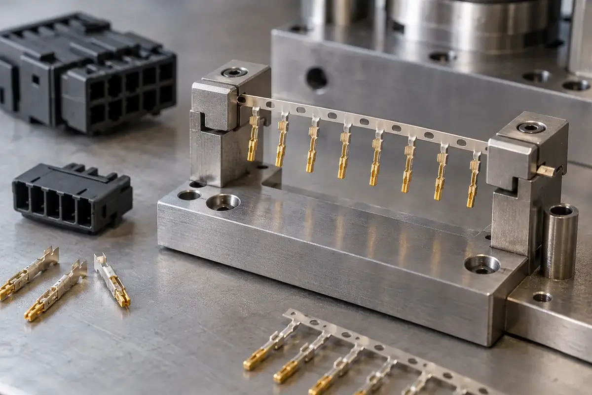
Flash on an exposed contact is a molding issue, not a reason to assume that any scraping or brushing method is acceptable. Removing unwanted polymer can mark the underlying finish or leave loose debris. If rework is proposed, define the method and its acceptance evidence separately. The guide to terminal shutoff and flash control addresses prevention at the tool interface.
Cleaning also needs a defined purpose. A solvent selected because it removes visible residue may interact with the polymer, alter a surface treatment or move contamination into a difficult-to-inspect region. Use a reviewed process for the specific materials and residue. A cleaner-looking part is not, by itself, evidence that its electrical contact surface remains suitable.
Some damage occurs after the mold opens. A terminal module can be ejected safely and then scraped during separation, cutoff or tray loading. Keep the protected-zone map active through these later operations. The same contact should not be treated as delicate during mold loading and as a convenient push point when placing the finished module into packaging.
Inspect the surface at meaningful stages
Incoming inspection establishes what was received. A post-loading or trial-stage review helps identify marks associated with tooling. Final inspection addresses the delivered component. Without this separation, a mark found after molding can be incorrectly attributed to the molding process even if it was present on the incoming strip, or overlooked because the incoming lot was accepted.
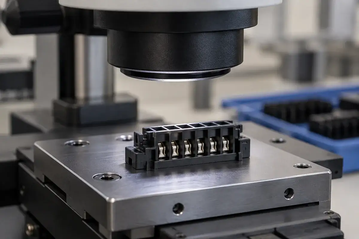
Define what magnification, lighting and orientation are needed to see the area of concern. Highly reflective surfaces can hide a scratch in one view and exaggerate harmless texture in another. Keep representative acceptance examples linked to the contact specification. Optical appearance can screen visible conditions, but it does not replace a required plating measurement or application-specific electrical evaluation.
Surface condition also affects the interpretation of mechanical checks. An unexpected mating force can involve contact geometry, surface friction, alignment or housing interference. The article on insert retention versus mating force explains why those measurements need different setups. Neither result should be used as a shortcut for identifying a plating defect.
When reviewing custom insert-molded connector components, include the finish map with the terminal and polymer geometry. For separate molded connector insulators, the assembly route still needs the same attention to protected contact zones. Clear touch points and inspection boundaries make the process easier to control than a general instruction to handle parts carefully.