
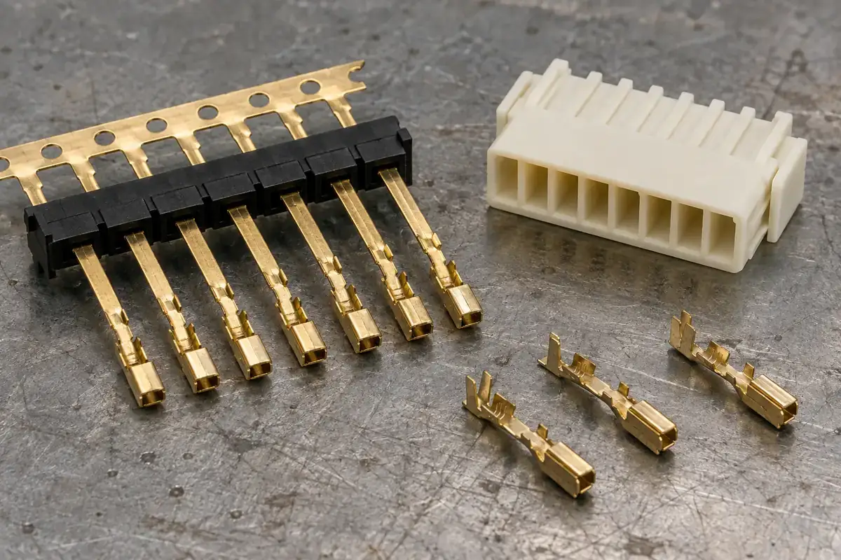
A connector can look almost identical from outside while being built in two very different ways. In one sequence, individual contacts enter an already molded housing. In the other, plastic forms around terminals held inside a mold. Choosing between them changes what locates the contacts, when defects become visible and which parts remain replaceable.
The useful starting question is therefore not whether insert molding is more advanced. It is which sequence gives the intended assembly a controllable relationship between its metal contacts and insulating body. An application with replaceable crimp contacts may favor a different architecture from a compact terminal module whose conductors must remain fixed relative to one another.
Product design illustrations accompany the assembly and manufacturing explanations below.
Where the contact position is established
With post-mold contact assembly, the empty housing provides cavities, stops and retention features. A contact travels through its cavity until the intended shoulder, latch or secondary lock establishes its final position. The contact and housing can be inspected independently before that operation, although successful inspection of both does not automatically prove that assembly was completed correctly.
Consider an illustrative socket housing containing several separate spring contacts. Each cavity needs enough access for insertion, and the retention arrangement must distinguish a fully seated contact from one that stops early. Molded cavity dimensions, contact forming, insertion direction and the assembled contact position all contribute to that distinction. A contact that is present is not necessarily a contact that is seated.
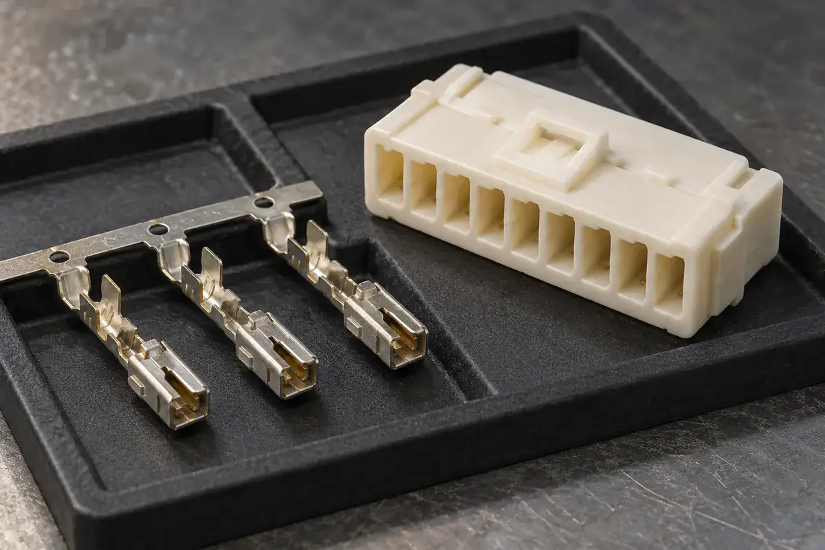
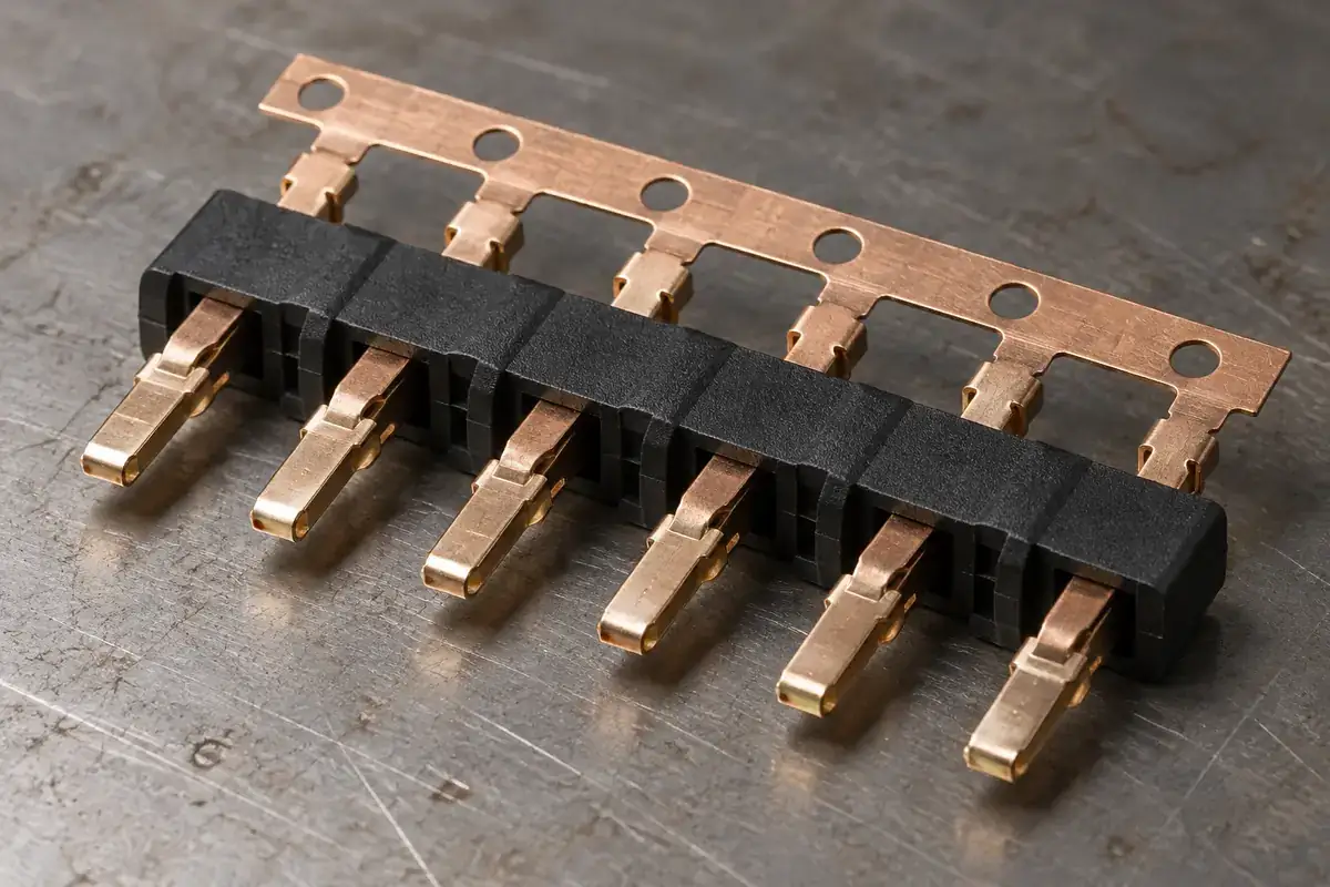
Insert molding moves some of that positioning work into the mold. A fixture holds the metal while polymer fills the intended insulating regions and solidifies. The general process is described in Protolabs’ insert-molding overview. For connector terminals, the additional concern is preserving exposed contact surfaces and electrical separation while creating that plastic body.
A terminal strip can keep multiple conductors in relation to a temporary carrier during loading. That does not make the stamped strip, molded body and final separated component geometrically identical. Carrier removal releases constraints, and forming or trimming may follow molding. The meaningful position is the position in the specified inspection state, rather than simply the position while the strip remains clamped.
Retention changes with the manufacturing sequence
A contact inserted after molding commonly relies on a feature that engages the housing after insertion. That could be part of the metal contact, the plastic body or a separate locking element. The design needs a usable insertion path as well as a controlled withdrawal resistance. Serviceability may be possible, but only if the chosen retention mechanism deliberately supports release.
In an insert-molded component, plastic can surround a retained portion of the terminal. Holes, shoulders or other deliberately formed features may help create mechanical capture. The design must still preserve the required metal cross-section and avoid placing sensitive contact surfaces inside the molded region. Neither route establishes a useful retention force without evaluating the actual geometry and loading direction.
It is also important to separate terminal retention from connector mating force. Pulling a terminal out of its plastic body loads a different interface from joining two connector halves. A module may retain its terminals securely while producing an unsuitable mating force, or the reverse. Our discussion of insert retention and mating force follows those load paths separately.
Repairability is a practical difference. A defective loose contact may be replaced before assembly, and some assembled systems permit controlled contact removal. Once metal has been captured in plastic, replacement may require rejecting the molded module instead. Whether that matters depends on the value of the components, the inspection sequence and the accessibility expected in service.
Tooling and inspection move to different places
For an empty housing, the mold primarily establishes the plastic cavity geometry. The contact-insertion process then needs its own location, orientation and seating controls. Those controls may involve simple fixtures or a more involved assembly station. Eliminating insert handling from the molding machine does not eliminate the need to position contacts; it moves that work downstream.
Insert molding adds terminal loading, support and metal-to-tool shutoff requirements. Thin metal features must remain in their intended positions during mold closing and filling. Contact plating and sensitive spring regions need suitable handling. A manufacturing review therefore considers the strip and the mold together, rather than treating a terminal drawing as a passive item placed inside an otherwise conventional cavity.
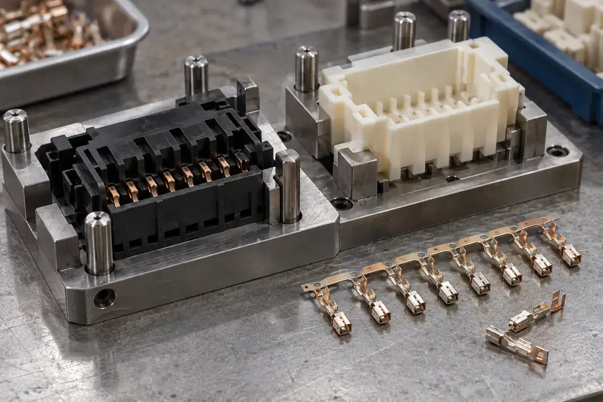
Inspection access can favor either sequence. Loose contacts allow direct observation of surfaces that later become hidden. An empty housing allows access to cavities before contacts obscure them. Conversely, an insert-molded module may provide a convenient plastic datum for checking several exposed terminals together. The inspection method should follow the functional relationship that must survive assembly.
Production quantity alone is an incomplete decision rule. A small batch with awkward loose-contact insertion can still justify a carefully designed molded module. A large batch may still use post-mold assembly because it needs multiple contact variants or a repairable architecture. The comparison should include tooling, terminal preparation, handling, inspection and the consequences of rejecting a combined component.
Choose the sequence around the interface
For a proposed terminal module, sketch the manufacturing states before comparing quotations: stamped or formed metal, supported inserts, molded body, trimmed carrier and final component. Mark which geometry locates each state. This simple exercise often reveals a hidden dependency, such as a carrier edge that is convenient for handling but poorly related to the terminal features that matter after trimming.
The same exercise for post-mold assembly should show the loose contact, empty cavity, insertion path, final stop and retention check. Compare the two sequences against the intended mating and board interfaces. Keep environmental and electrical qualification as separate requirements for the completed assembly; a particular molding method does not itself establish a connector rating.
Our custom insert-molded connector components cover the metal-and-plastic module discussed here. If the requirement is primarily a separately molded insulating shell, the connector insulator page provides a different starting point. The distinction helps define the manufacturing responsibility before tooling decisions become difficult to reverse.
Once insert molding is the appropriate route, the next useful discussion is how the metal will be located and supported. Leadframe carrier location explains why transport features, mold references and final component datums need to be connected deliberately. That relationship is often more consequential than simply choosing between two process names.