
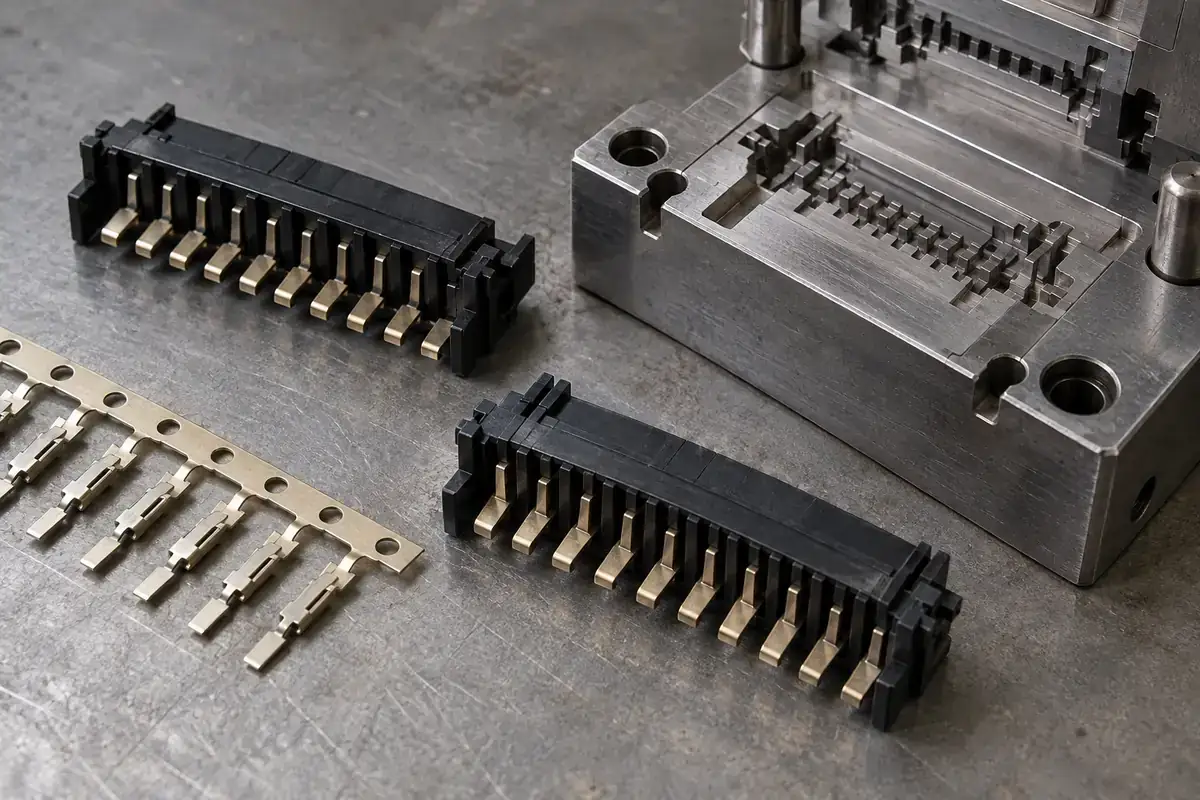
A thin connector wall is rarely an isolated strip of plastic. It connects to ribs, surrounds metal and may divide one conductive path from another. Filling that wall therefore means navigating a network of narrow passages whose boundaries include both tool steel and terminal inserts. The final few millimeters of flow can be more revealing than the overall component size.
When a short shot appears, simply increasing a machine setting does not explain why the cavity stopped filling. The material may be cooling along a long restricted path, air may lack an escape route, or an insert may have changed the local opening. A useful investigation follows the flow path and the insert condition together.
Product design illustrations accompany the assembly and manufacturing explanations below.
Follow the melt around the terminals
Each terminal can divide the approaching flow into separate paths. Those paths travel around the metal and may meet again downstream. The meeting location depends on the cavity geometry, gate arrangement and process conditions. It is not necessarily centered behind the terminal, particularly where adjacent ribs or changes in section give one path a different resistance from another.
Imagine a row of flat contacts captured in a narrow plastic crossbar. A gate near one end creates a different progression from a gate entering across the width of the row. One layout may expose successive terminals to filling in sequence, while another approaches several together. Neither arrangement is automatically superior; the connector injection-mold review should consider filling, insert support and the functional location of meeting fronts together.
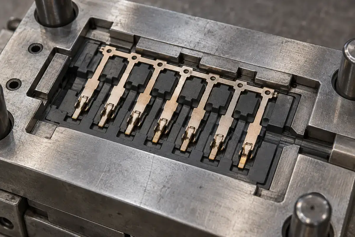
Terminal thickness and position are part of the flow geometry. If a finger moves toward one cavity wall, one passage becomes narrower while another becomes wider. The resulting imbalance can make the molded plastic look like a process-only problem even though the initiating change was mechanical. Inspecting insert position alongside fill behavior helps avoid that mistaken separation.
The polymer candidate changes the picture again. A flow path that is feasible for one specific grade may be unsuitable for another, even within a familiar material family. Our comparison of LCP, PBT and PA9T connector materials explains why the grade, orientation and sample condition should remain visible throughout development.
A weld line has a location and a loading context
When divided flow fronts rejoin, the resulting region deserves attention in relation to the component’s function. A meeting region across a lightly loaded wall is a different concern from one crossing a thin terminal-retention feature. The question is not merely whether a weld line exists, but where it is and how that region is loaded or used.
Orientation-sensitive materials make this more important. Celanese’s Vectra design guide discusses flow orientation and weld-line behavior in LCP. This supports reviewing the actual meeting pattern; it does not provide a universal strength reduction that can be assigned to every thin-wall connector feature.
A mold-flow analysis can help compare proposed gates and flow paths before cutting steel. Its value depends on the material data, geometry and assumptions used, including how the inserts and local restrictions are represented. Treat its output as a development aid that guides observations and trials, rather than a substitute for checking the molded component.
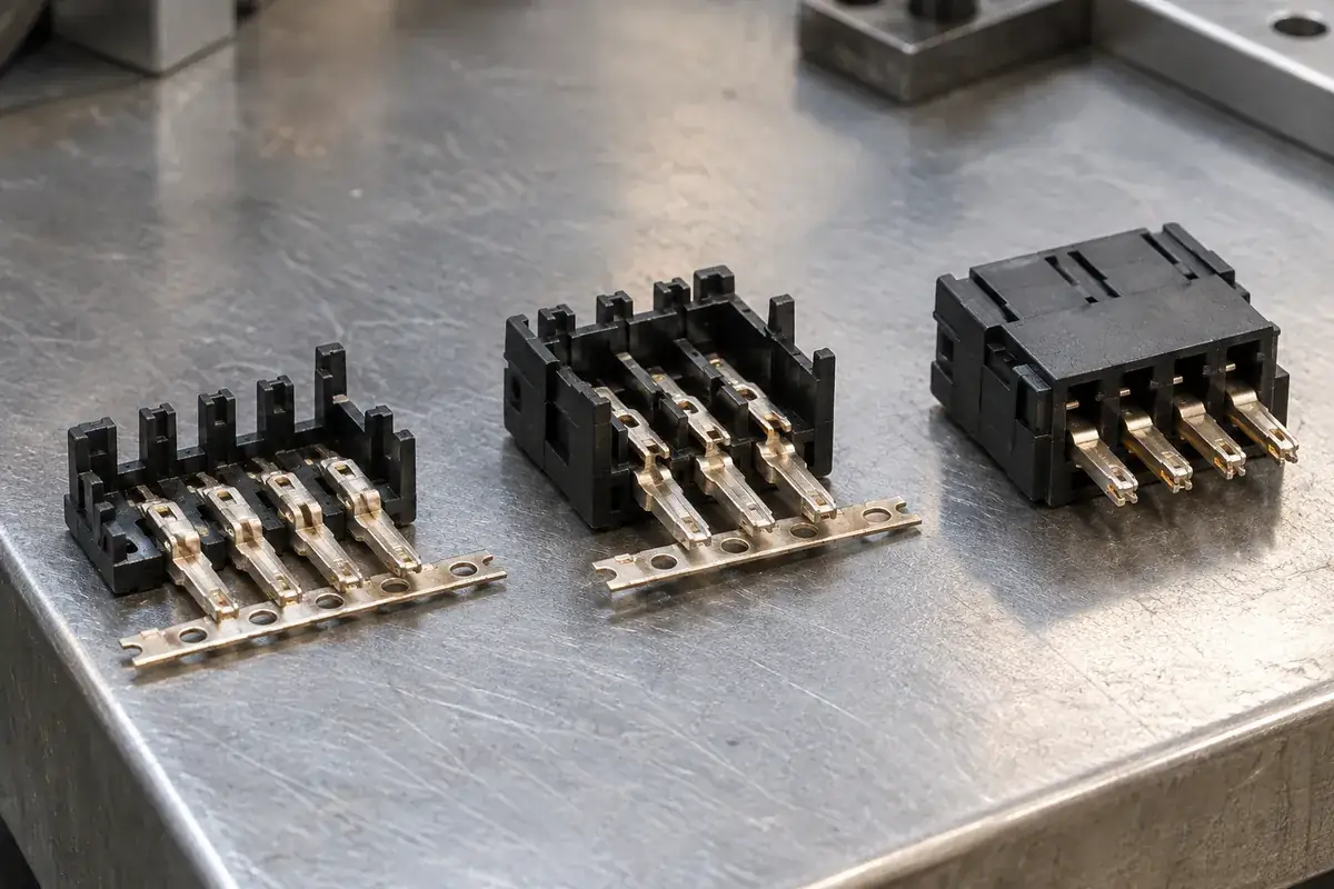
Physical filling studies can add another view of the progression. Controlled partial fills, interpreted with the process settings and insert condition, may reveal which region fills first and where fronts converge. Keep the sequence associated with the specific tool and material used, and compare the same cavity regions rather than treating unrelated partial samples as a continuous progression.
Give displaced air a deliberate route out
As polymer occupies the cavity, the air already inside must leave. Thin branches, blind pockets and areas behind inserts can create difficult escape paths. A gate arrangement that looks efficient from the main runner may still leave an isolated end region. That is why vent review should follow the anticipated filling sequence rather than merely distribute vents evenly around an outline.
For LCP precision molding, Celanese’s processing guide discusses vent design, trial observations and the relationship between filling conditions and defects. Use the applicable grade guidance and actual tool behavior. A vent dimension or machine recipe should not be transferred uncritically from another resin or connector geometry.
A useful vent has a controlled land and a route away from the cavity. Its presence on a drawing does not establish that the route remains effective in operation. Deposits, mating surfaces or surrounding tooling may alter the path. Maintenance access and a repeatable inspection method therefore belong in the tool discussion, especially when a small change can affect a thin terminal-adjacent wall.
Process changes have consequences elsewhere
Increasing filling speed may help a narrow section fill before cooling restricts flow, but it also changes the loading applied to inserts and the way air is displaced. The response depends on the material and tool. A faster setting that completes one rib may introduce another concern, so success should be evaluated across the component rather than at the former short-shot location alone.
Likewise, additional pressure cannot make an unsupported terminal rigid or turn an accidental gap into a suitable vent. The fill requirement must be reconciled with the shutoff boundary around exposed contacts. The article on terminal shutoffs and flash control examines why those boundaries should be investigated before pressure becomes the default adjustment.
Compare trials using defined observations: fill progression, terminal position, critical dimensions, the condition of exposed contacts and any relevant retention features. Keep the material and conditioning record attached to those observations. A filled cavity is necessary, but it is not sufficient evidence that the resulting connector component meets all its intended functions.
Review the thin wall as part of the complete module
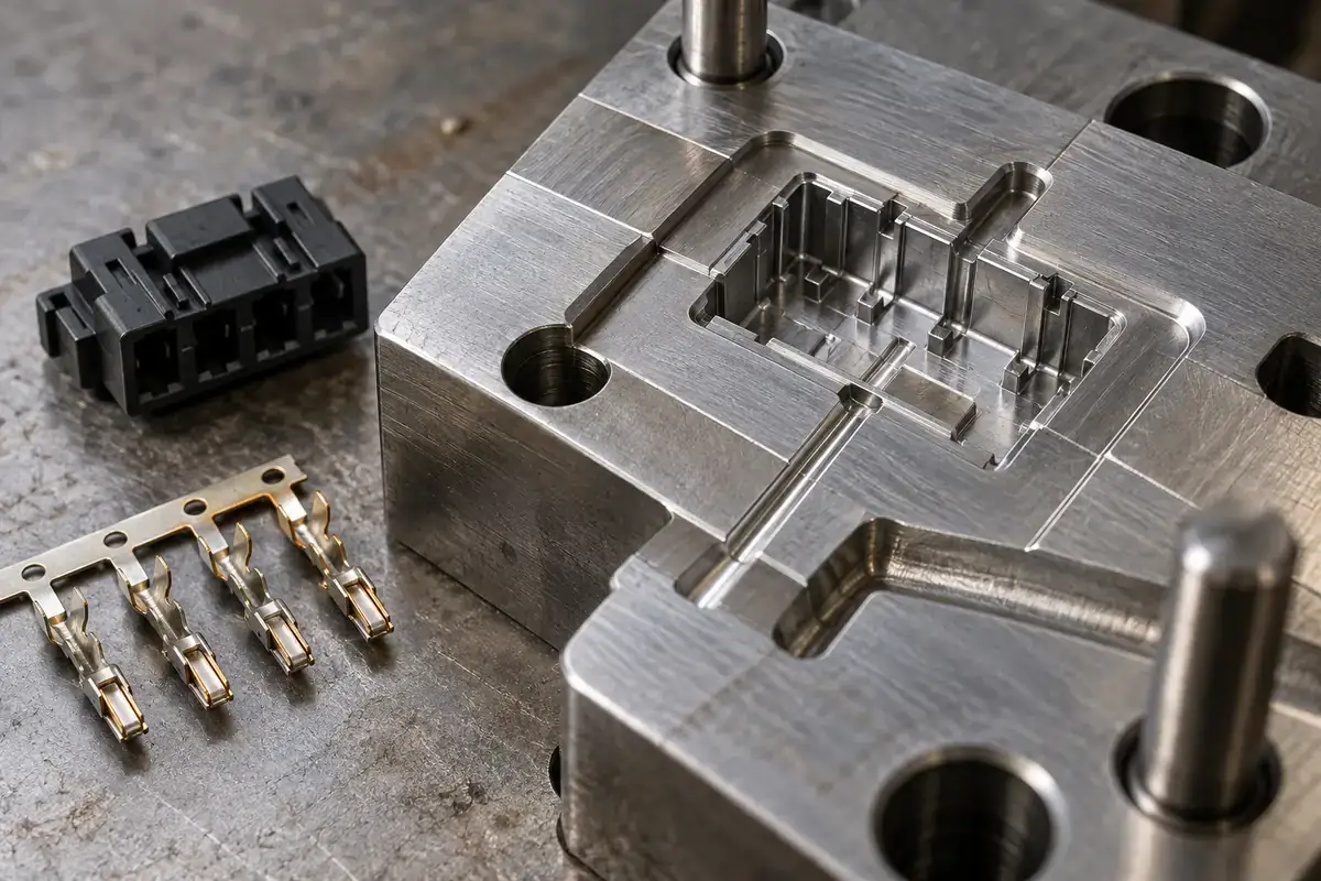
For custom insert-molded connector components, useful early information includes the terminal geometry, intended plastic coverage and the final assembly interfaces. These reveal where a wall is electrically or mechanically significant, where support is possible and where gate or vent access might interfere with later operations.
Thin-wall feasibility is ultimately a relationship between a named material, the metal inserts, the cavity layout and a controlled process. Our insert-molding service addresses that combined sequence. Following the flow around the real terminal geometry produces a more useful development discussion than selecting a universal minimum wall thickness from a generic chart.