
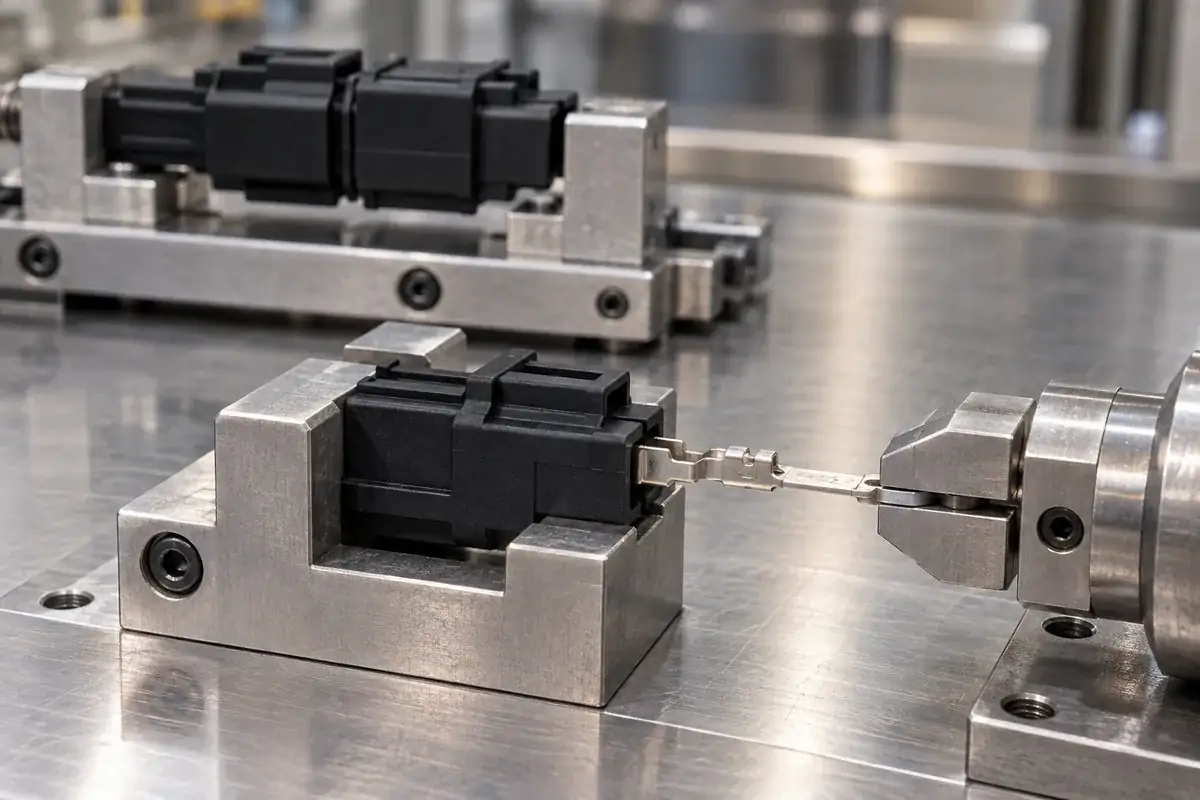
A connector that feels difficult to plug in does not necessarily hold its terminals securely. The effort felt during mating belongs to one interaction; the force needed to move a terminal relative to its insulator belongs to another. Mixing those questions can produce an impressive-looking test report that does not actually demonstrate the required mechanical function.
For an insert-molded component, begin by naming the interface. Is the concern a metal contact moving inside a molded crossbar, the crossbar moving inside an outer housing, or two connector halves engaging? Each has a different load path. The word retention is useful only when the retained item and the item retaining it are explicitly identified.
Product design illustrations accompany the assembly and manufacturing explanations below.
Identify which interface is being loaded
Contact retention in the molded body concerns the relationship between the terminal and the polymer around it. The test must load the terminal while supporting the relevant insulating structure. A fixture that clamps both together can prevent the relative movement being investigated. It may record the strength of the fixture arrangement instead of the effectiveness of the retention feature.
IEC 60512-15-1 addresses contact retention under axial loads in an insert or housing. Its scope is a useful reference when agreeing a method, but the applicable detail specification still determines the project requirements. Listing the standard number beside an arbitrary pull force does not establish a compliant test or a suitable acceptance limit.
Insert retention in an outer housing is a separate interface again. A terminal can remain secure in its crossbar while the whole crossbar shifts in the surrounding shell. For a modular connector, identify which component is supplied and which assembly steps remain outside that supply scope. This prevents a component test from being presented as proof of the completed connector's mechanical performance.
Mating force measures a different interaction
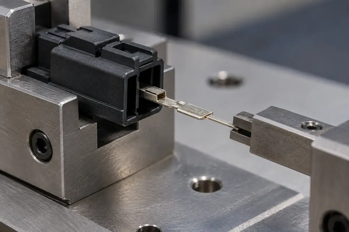
Mating involves contact engagement and may also involve housing guidance, latches, seals or other features. A complete assembly force can therefore contain contributions unrelated to the contact's retention in the polymer. To interpret the result, record which features are active and which are intentionally excluded, rather than using one force value for every mechanical function.
IEC 60512-13-2 describes insertion and withdrawal measurements with specified auxiliary effects excluded. That distinction matters: a test following that scope is not the same as the total effort a user experiences when engaging every latch and seal in a finished product. Both questions can be relevant, but they need different definitions.
Contact geometry and surface condition can influence mating behavior. Samtec's contact design discussion connects contact spring behavior with insertion, withdrawal and normal forces. The practical implication for a custom module is to investigate the contact pair and alignment rather than assuming a high mating force demonstrates strong molded retention.
Consider a hypothetical terminal that sits too far forward in its insulator. The connector may still engage, but the contact can encounter an unintended region of its mate. The resulting resistance might rise even though the retention feature has not become stronger. Conversely, a low mating force could reflect the intended contact design rather than a loose terminal.
Build fixtures around the question, not the machine
For a terminal-retention evaluation, support the molded body close enough to represent its intended reaction path without covering the retention region in a way that adds artificial restraint. Align the applied load with the specified direction. An off-axis grip can bend a terminal before it meaningfully challenges its retention, producing a different failure mechanism.
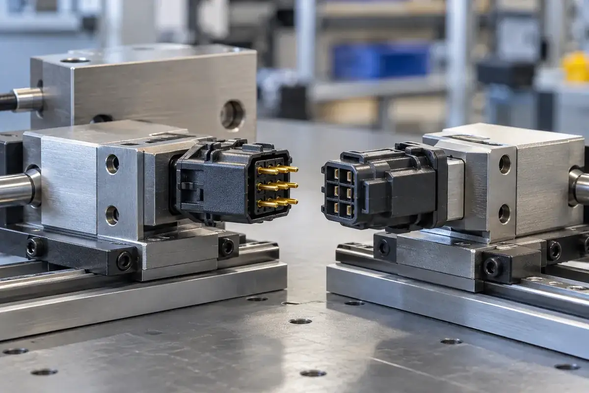
For mating-force measurement, the relationship between the two halves matters. Define the mating component revision, alignment, approach direction and travel. A fixture that corrects every misalignment may answer a different question from an assembly where guidance must come from the connector itself. Neither fixture is inherently right; it must match the test objective and the specified method.
Capture displacement or the relevant observation alongside force when the method calls for it. A terminal may move without fully escaping, or return partly after the load is removed. A single maximum-force reading can conceal that behavior. Record whether the criterion concerns initial movement, residual position, complete extraction or damage, using the agreed test procedure.
Use separate specimens when a test changes the component in a way that would affect the next result, unless the specified qualification sequence deliberately requires the same specimens. Pulling a terminal toward failure and then reporting the same unit's mating force as an unaffected baseline would mix two different conditions. Sample history belongs in the record.
Connect results to the manufacturing investigation
If terminal retention changes between trials, review the retention geometry, polymer fill around the insert, material condition and visible damage. If mating behavior changes, inspect alignment, contact shape and surface condition as well as the housing. Some causes overlap, but keeping the measurements separate narrows the investigation rather than forcing every symptom into a molding explanation.
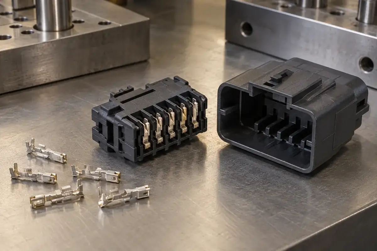
The guide to plated-contact handling covers one important contributor that can be missed in a purely dimensional review. The article on carrier cutoff and released geometry covers another. Measure the component in its intended delivered state when that state governs the requirement, not only while its carrier makes alignment easier.
Mechanical results do not independently establish current capacity, insulation performance, environmental sealing or signal integrity. Those requirements belong to the completed connector and its application-specific validation. Keeping that boundary clear improves the usefulness of the mechanical evidence: it shows exactly what was evaluated and leaves the remaining functions available for their appropriate tests.
When developing a custom insert-molded connector component, define the retained item, load direction and support condition before selecting a fixture. If the project uses a separate molded insulator, include its assembly interface too. The result is a mechanical acceptance plan that distinguishes secure terminals from an acceptable mating experience.