
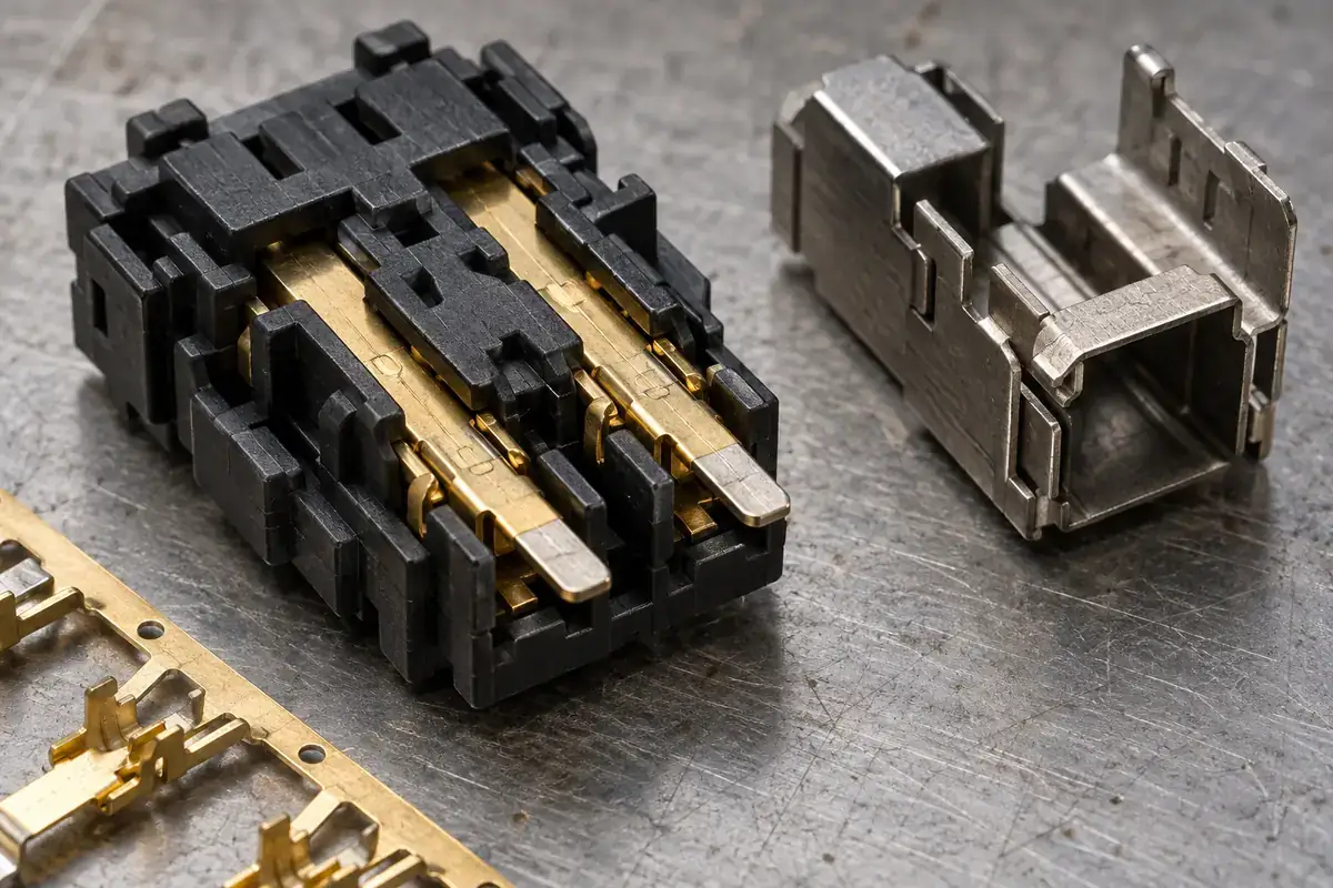
A very small amount of plastic in the wrong place can matter more than a larger cosmetic mark elsewhere on a connector component. The critical question is not simply whether flash is visible. It is whether polymer has entered a region intended for contact, assembly clearance, terminal movement or another defined function.
Insert molding makes that boundary particularly important because the metal passes through the edge of the molded plastic body. The tool must allow selected terminal regions to remain exposed while containing polymer around the regions that should be insulated or retained. That transition is a functional design feature, not merely the edge of a decorative surface.
Product design illustrations accompany the assembly and manufacturing explanations below.
Define where plastic must stop
A connector terminal can contain a mating area, a retained section, a board termination and a temporary carrier feature. These regions do not necessarily have the same sensitivity to polymer coverage. Start by identifying the actual keep-clear areas and their purpose. A general note demanding an attractive surface cannot communicate the same requirement as a defined functional boundary.
For an illustrative flat terminal, the molded crossbar may intentionally surround the middle section while the mating tip remains bare. The transition location affects both retention and contact access. Moving that transition to make the tool easier to build may reduce the available contact region or change the unsupported length. Bring those keep-clear boundaries into the precision connector mold review so tooling access and component function are evaluated against the same drawing.
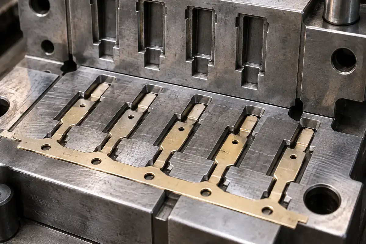
A shutoff is the local arrangement that prevents polymer from entering the region beyond that boundary. Protolabs’ discussion of mold shutoffs explains the connection between a sealing interface, wear and flash. Its steel-to-steel examples provide background; they are not a universal dimensional prescription for closing a tool against a delicate connector terminal.
At a metal insert, the terminal itself becomes part of the local fit condition. Its thickness, flatness, edge condition and seated position influence the gap the tool encounters. A tool designed around a nominal terminal dimension still has to accommodate the defined variation of the incoming metal without allowing leakage or damaging the insert.
Investigate the interface before changing pressure
When flash appears, reducing molding pressure may seem like the quickest response. That can change the symptom without correcting the underlying fit. If the terminal is not seated, a support is worn or the incoming strip has changed shape, the resulting gap remains. A process adjustment may then create incomplete filling somewhere else while leaving the interface unstable.
The opposite response can be equally misleading. Increasing force at the shutoff may improve contact locally while marking plating, bending the terminal or preventing the strip from seating elsewhere. The design needs an appropriate contact arrangement and support path. There is no useful universal instruction to clamp every insert more tightly until flash disappears.
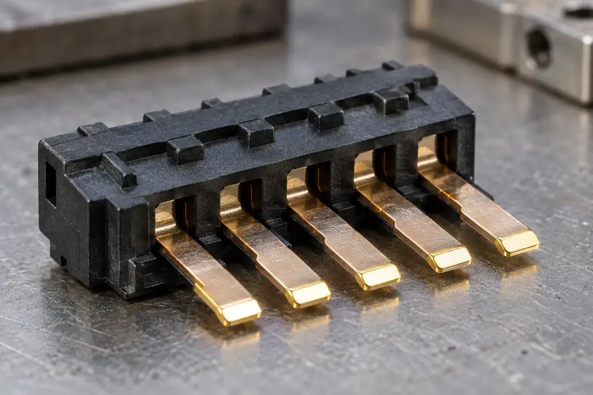
Observe where flash begins and whether the pattern repeats across terminal positions. A consistent local feature suggests a different investigation from random variation between strips or cavities. Record the terminal condition, tool position and molding state associated with the observation. That makes the result more informative than a photograph labelled only “flash problem.”
Carrier location is part of this investigation. A terminal that shifts slightly relative to its support may change the local shutoff even when its thickness is acceptable. Carrier location and terminal support explains why a well-located rail does not guarantee that every finger is seated correctly at the plastic boundary.
Flash and venting serve opposite purposes
The cavity needs a route for displaced air and process gases, but that route must not become an uncontrolled path for polymer into a protected region. A designed vent is located and sized for its task. An accidental gap around a terminal is not an acceptable substitute simply because it allows air to escape during filling.
Thin sections can make this balance more visible. The process may need to fill narrow ribs around inserts while maintaining a clean boundary at their exposed ends. Changing material or filling conditions can alter that balance. Treat the shutoff, the gate and the vent arrangement as connected features rather than optimizing one interface in isolation.
Tool maintenance also matters. Deposits or damage on a small locating or shutoff surface can change seating without being obvious in a general cavity photograph. Inspection should focus on the surfaces that establish the local relationship. Any cleaning method must be compatible with those surfaces and the terminal condition; aggressive handling can create a new problem while removing a deposit.
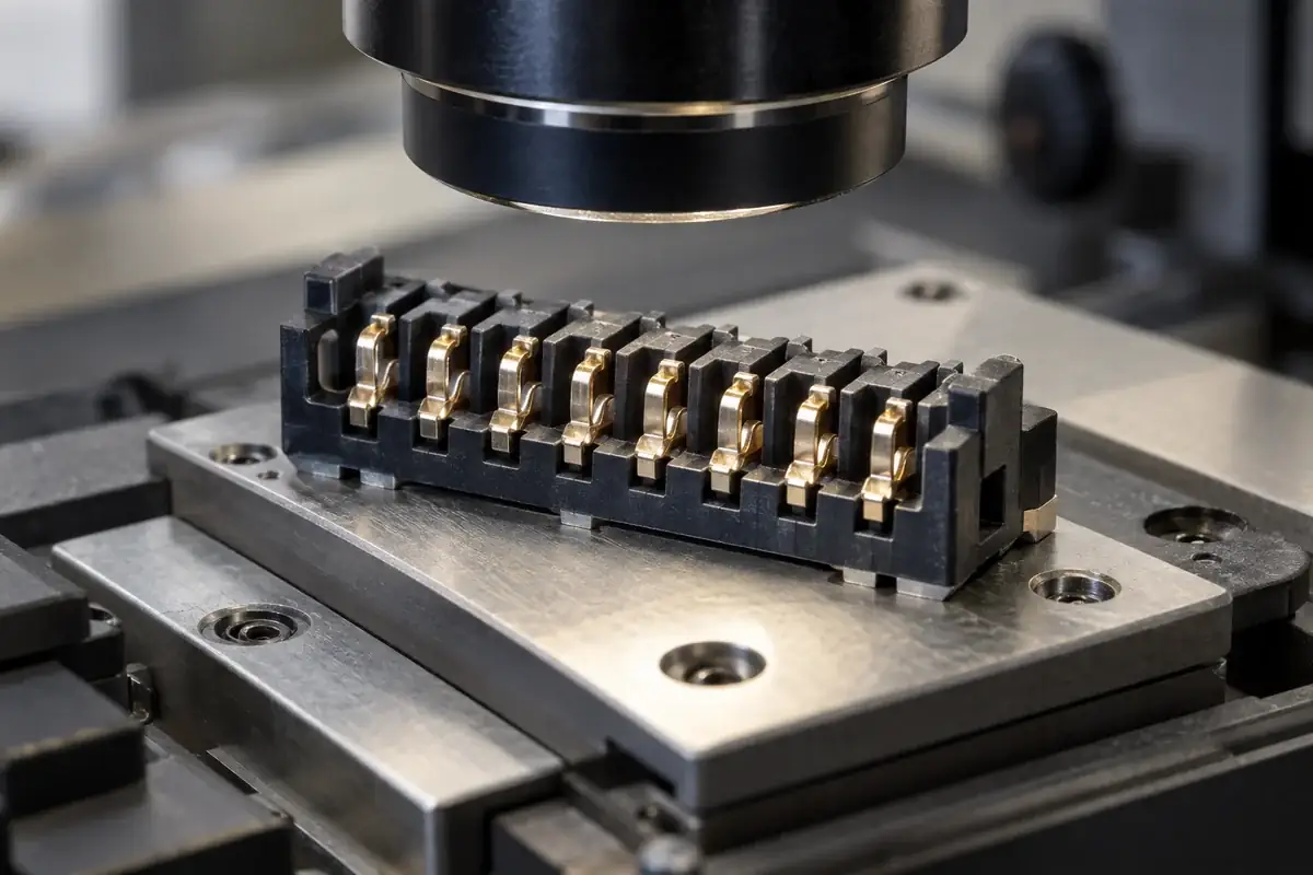
Inspect the region that the assembly will use
A low-magnification visual check may detect a large fin while missing a thin film across a contact area. Conversely, a highly magnified image can make an inconsequential edge feature look alarming without revealing its relationship to the mating interface. Establish the inspection view and acceptance criterion around the function of the particular region.
A functional assembly check can add useful evidence, but it should not replace observation of the actual boundary. A connector may mate despite local polymer contamination, and a fit check does not demonstrate electrical contact performance. Keep geometric, visual, mechanical and electrical evaluations distinct so that one passing result is not used to imply another.
Removing flash after molding also needs a defined scope. Access near plated contacts may be limited, and a trimming operation can mark metal or leave loose material. If finishing is proposed, evaluate the resulting component and cleanliness rather than assuming that any visible excess can be removed harmlessly. Repeated corrective trimming may signal that the upstream interface deserves attention.
Put the boundary into the manufacturing discussion
For custom insert-molded connector components, identify the intended plastic coverage on the terminal drawing as clearly as the final outside shape. Include the sensitive contact regions and the metal condition expected at molding. Those details give the tool review a concrete interface to solve instead of an undefined request for “zero flash.”
The related thin-wall filling and venting article explains the cavity-side problem, while our insert-molding process page outlines the broader sequence. A dependable boundary comes from a compatible terminal, support arrangement, tool condition and molding process working together.