
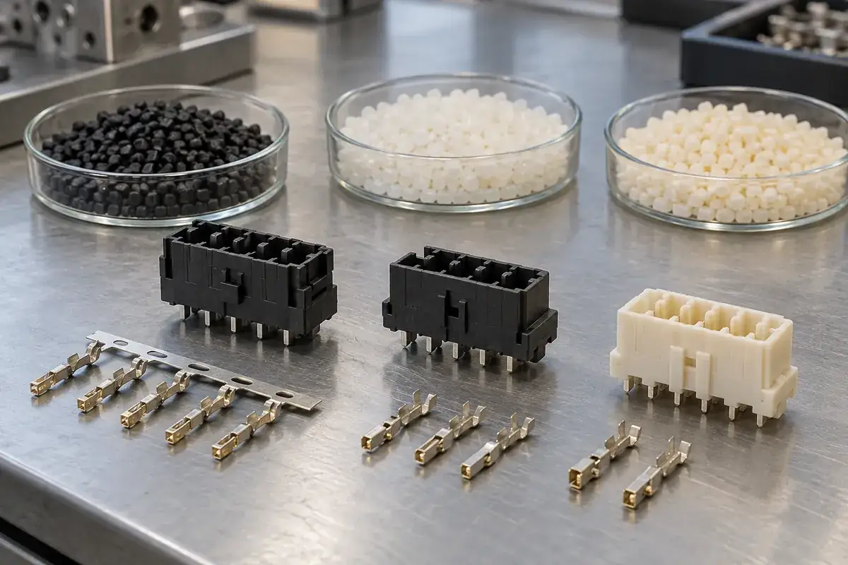
A connector drawing that says only “LCP,” “PBT” or “PA9T” leaves several important decisions open. Each name covers materials with different reinforcement, processing behavior and performance. Even when two candidates can form the same outline, they may produce different terminal movement, local shrinkage or responses to later assembly conditions.
That makes the material comparison a geometry and process discussion as well as a datasheet discussion. A thin insulating rib between adjacent contacts has different demands from a thick support wall around a terminal shoulder. A material selected for one region can create difficulties elsewhere, particularly when a metal insert constrains the plastic as it cools.
Product design illustrations accompany the assembly and manufacturing explanations below.
Start with the conditions the component will experience
Separate molding conditions from service conditions and downstream assembly exposure. The polymer must process around the terminals without damaging their intended condition. The finished component must then tolerate its specified assembly and operating environment. These are related requirements, but a high processing temperature is not a direct statement of useful service temperature.
For example, a board-mounted module might face a defined thermal assembly profile, while another connector component is assembled without that exposure. A wet environment introduces a different set of considerations again. Describing the actual sequence avoids selecting a material merely because a brochure associates its family with “electronics” or “high temperature.”
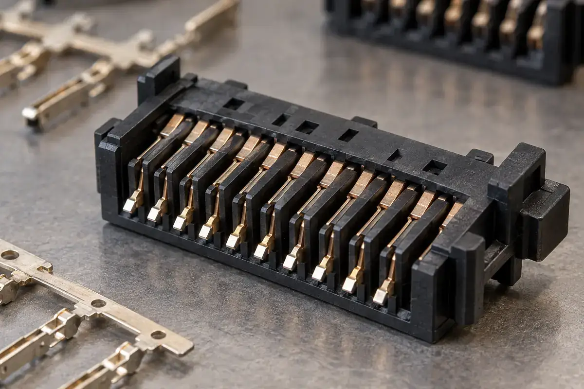
Electrical requirements also need a defined scope. A resin classification belongs to a particular material and evaluation condition; a completed connector includes metal geometry, insulating distances, contamination exposure and assembly details. Material selection can support the design, but it cannot replace evaluation of the actual connector configuration or justify a generic current or voltage rating.
LCP brings flow opportunities and directional behavior
LCP is often considered when a connector has thin sections and fine features. The same flow-induced orientation that helps characterize its molding behavior can make properties direction dependent. Celanese’s Vectra LCP design guide discusses orientation, anisotropic shrinkage and weld-line considerations rather than treating shrinkage as one universal number.
In a terminal module, the melt divides around metal inserts and narrow ribs. Local flow directions can differ from the overall direction between gate and cavity end. Consequently, a convenient datasheet value measured in one direction does not describe every dimension around the terminal row. The proposed gate arrangement and the region being measured matter to the interpretation.
This is why “LCP means no warpage” is an unhelpful shortcut. Grade, reinforcement, flow path, wall distribution and restraint from the inserts all influence the outcome. A small component can still develop a meaningful local distortion at an interface. The appropriate question is whether a particular grade and tool arrangement produce the required geometry in the specified final state.
PBT and PA9T offer different sets of candidates
PBT should also be treated as a portfolio rather than a single material. BASF’s Ultradur overview describes unreinforced, reinforced and modified options, including grades aimed at electrical applications. That variety is a reason to identify the intended grade early, not a reason to assume that every PBT meets the same connector requirement.
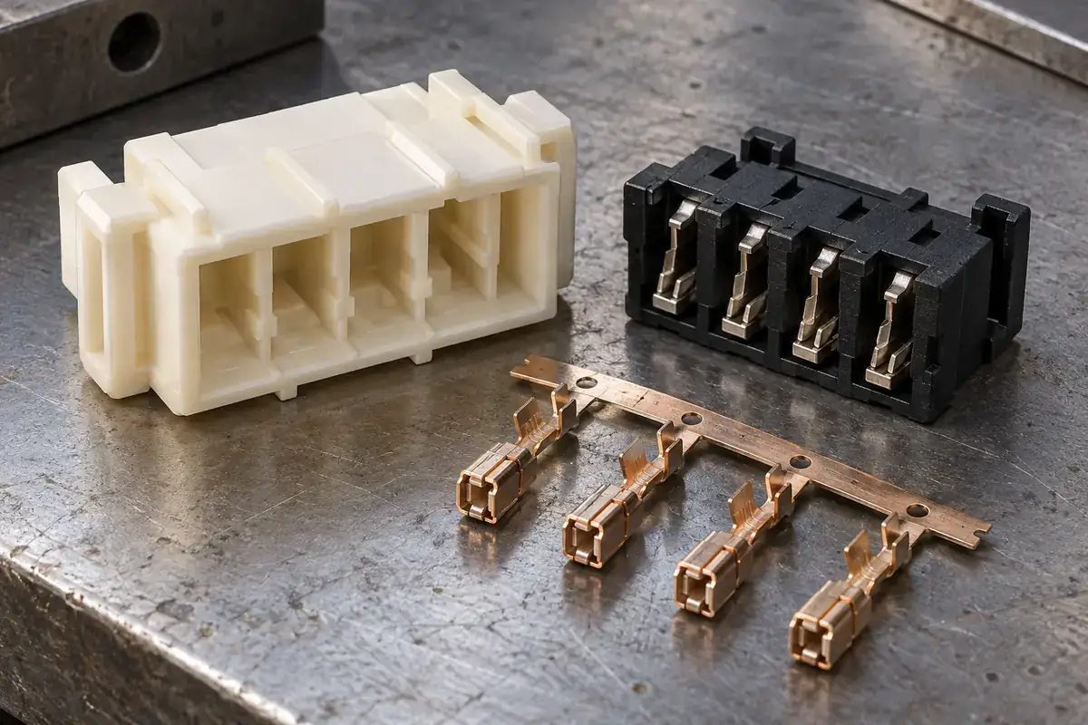
A relatively substantial insulating support may allow a different balance of flow, toughness and stiffness from a tightly packed thin-wall module. Yet changing from a thin design to a thicker one can also change cooling and constraint around the terminals. Comparing candidates on an unchanged outline is useful, but redesigning the outline around a candidate may be necessary.
PA9T is another family used for demanding connector applications. Kuraray’s GENESTAR information explains its low water absorption and heat-related attributes. Those manufacturer descriptions identify a useful candidate family; they do not make every grade interchangeable or remove the need to review the exact thermal exposure and moisture condition for the proposed component.
Moisture history deserves an explicit place in the comparison. Incoming material condition, drying, storage and the condition of molded samples can affect what a trial actually demonstrates. Comparing a freshly molded specimen of one candidate with a differently conditioned specimen of another can obscure whether the difference comes from formulation, conditioning or geometry.
The metal insert changes the material problem
A free plastic test specimen can deform differently from plastic captured around metal. Terminal shoulders, holes and embedded lengths create local constraints. As the component cools and later experiences temperature changes, those constraints influence where displacement or stress can develop. The interface therefore needs attention even when the polymer’s general datasheet properties look comfortable.
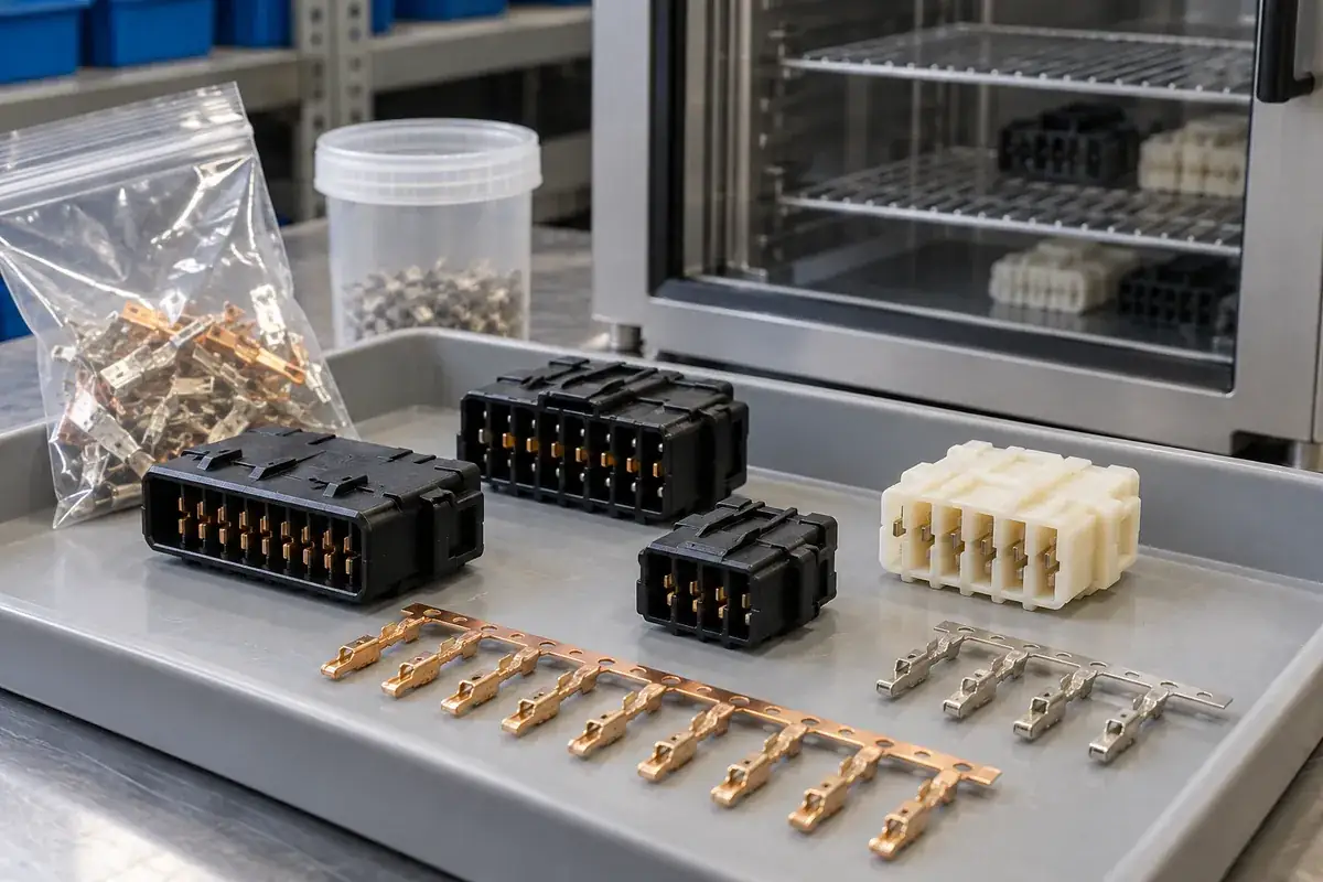
Flowability is similarly more than an ability to reach the far end of a cavity. A candidate that fills a thin rib may require a different filling pattern or support arrangement to avoid moving a slender terminal. The relationship between molding flow and terminal movement belongs in the same development discussion as the material selection.
Plating and exposed contact regions add another interface to review. The proposed molding temperature, handling method and any subsequent cleaning must be compatible with the actual terminal specification. Avoid judging that compatibility from the polymer alone. The metal substrate, plating system, contact function and processing sequence each contribute information that the resin datasheet cannot supply.
Compare a controlled set of candidates
A useful trial compares named grades under documented conditions and checks the same functional dimensions in the same assembly state. Record the gate and filling arrangement, the conditioning history and whether the carrier remains attached. Otherwise, an apparent material improvement may actually reflect a different support condition or a changed measurement reference.
Keep an approved alternative separate from an unrestricted substitution. Two grades with the same base-polymer name can differ in reinforcement, color formulation or other characteristics relevant to molding and qualification. A proposed change should return to the affected requirements and evidence, rather than inheriting approval solely because the material family remains the same.
For custom insert-molded connector components, the material decision becomes more useful when it accompanies the terminal drawing and intended assembly sequence. Our insert-molding service provides the process context, while thin-wall filling and venting explains why the tool and material cannot be selected independently.