
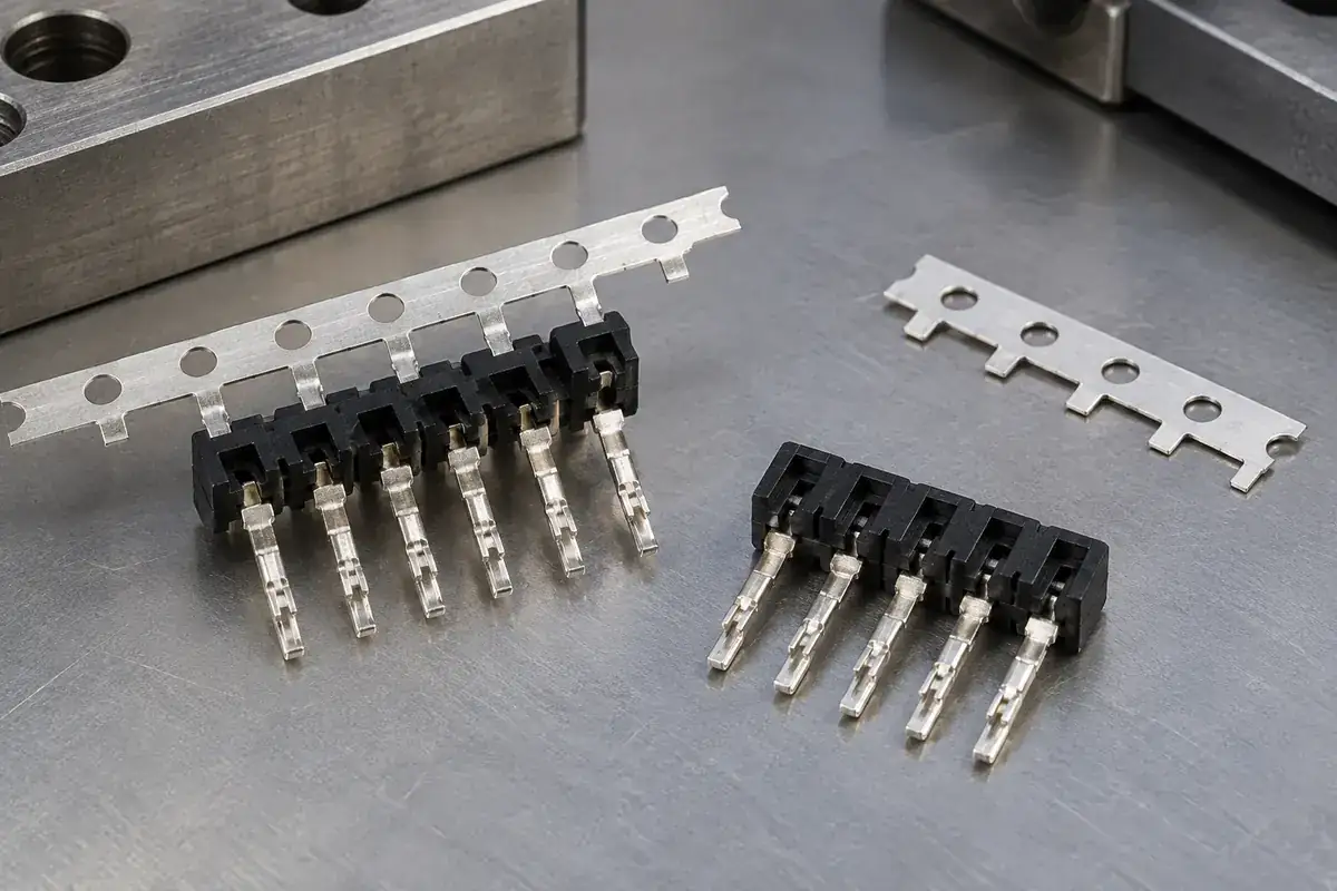
A connector terminal module can look straight while attached to its carrier and sit differently after the rail is removed. That does not automatically mean the cutting tool bent it. The carrier was also a restraint. Removing it changes which parts of the metal-and-polymer assembly are free to move, so the released geometry deserves its own inspection condition.
The distinction matters when troubleshooting. A cutting operation can impose a load, release an existing load, or do both. If those mechanisms are treated as one generic warpage problem, a team may keep adjusting the cutter while the underlying asymmetry remains in the molded module. A staged comparison is more useful than judging only the before-and-after photographs.
Product design illustrations accompany the assembly and manufacturing explanations below.
The carrier does more than transport the contacts
A stamped carrier connects multiple terminal positions and provides handling and location features. While attached, it can restrict motion that would be possible in a separate finished part. The degree of restraint depends on the rail, tie tabs, terminal shape and how the assembly is supported. A thin tie can still matter if it acts at the end of a long flexible feature.
After molding, metal and polymer remain connected through their retention geometry. Their thermal and mechanical responses are not identical, and the molded polymer can have direction-dependent shrinkage. Releasing a carrier may therefore reveal a shape that was previously restrained. This is a possible mechanism to investigate, not a prediction that every carrier-based connector will distort after trimming.
Celanese's Vectra LCP design guide describes the influence of flow orientation and part geometry on shrinkage and warpage. That material guidance helps frame the investigation. It does not provide a universal cutoff allowance or establish the released shape of a particular insert-molded module.
Observe the stages without changing the reference
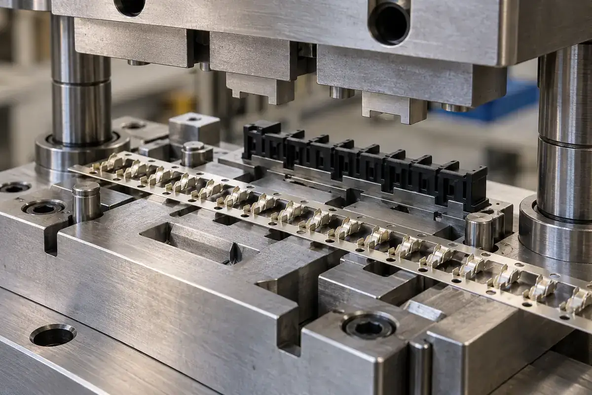
Record a sample while it is still on the carrier, after the relevant cut, and in its final supported or assembled condition. Use the same physical features to compare terminal position whenever possible. If one measurement references the carrier rail and another references the plastic body, an apparent movement can partly reflect the change of reference rather than the component itself.
Keep the time between operations consistent enough for the investigation. Comparing a warm freshly molded strip with a cooled released part adds another variable. The objective is not to prescribe one universal waiting period. It is to know the thermal and conditioning state of each observation, then choose a condition representative of the drawing and the actual downstream process.
A fixture can conceal the effect being studied. Pressing a released module flat against a plate may restore the earlier appearance while introducing forces that are absent in service. Conversely, an unsupported part may exaggerate a movement that the intended assembly constrains. Define whether the acceptance requirement applies to a freely supported component or a specified assembled state, and inspect accordingly.
The carrier-location article explains how the rail establishes the starting condition. The cutoff review begins where that function ends. Retain the identity of the strip position and molding cavity so a repeated pattern can be distinguished from occasional damage during transfer or loading into the trim fixture.
Separate cutting loads from released restraint
A cutter needs a reaction path. If the fixture supports the rail but leaves the molded crossbar poorly supported, the cutting force can travel through the terminals and their polymer retention regions. Review where the component bears against the tool at the instant of separation, rather than assuming that the nearest clamp provides adequate support.
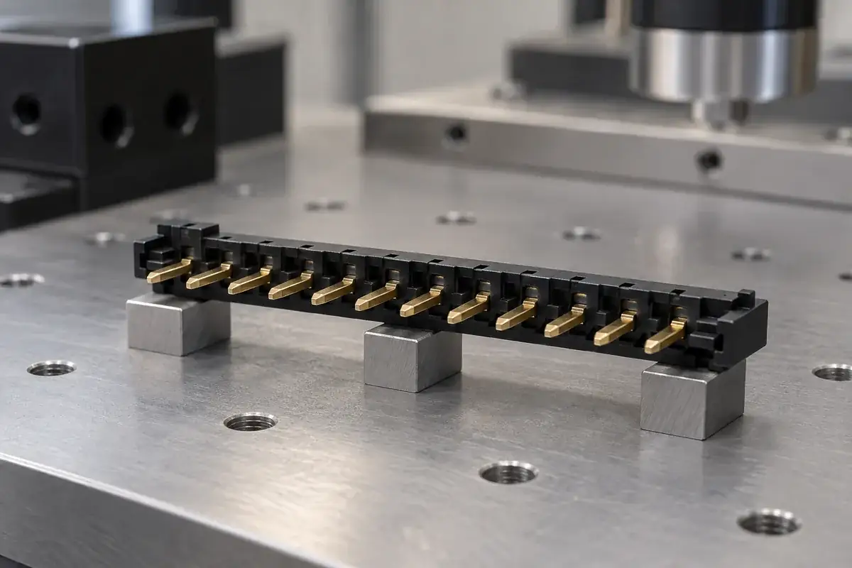
Cut clearance, alignment and tool condition influence the separation event, but a change should be tied to an observed mechanism. If the terminal bends locally beside the cut, inspect the cutting and support arrangement. If the whole module takes a smooth bow after several ties are released, investigate restraint and molding history as well. These are clues for trials, not conclusive diagnoses.
Cutting sequence can change the temporary load path. Releasing one side first may leave the other side carrying an asymmetric restraint. A different sequence may be worth evaluating when geometry permits, but it should not be presented as an automatic solution. Compare the final released component and the condition of the cut edges, not only how easily the operation runs.
TE's SIAMEZE application specification illustrates why cutoff details and burr allowances belong to the particular terminal drawing. That document concerns its own terminal system, not this insert-molding process. The transferable lesson is to define the intended cut geometry rather than treating carrier removal as an unspecified finishing action.
Keep corrective actions tied to the final component
If released restraint is implicated, review the molded crossbar, terminal layout and filling pattern together. A local thick section or an asymmetric polymer envelope may deserve attention, but adding material can also change cooling and flow. The goal is not simply to make the part stiffer while attached to its rail; it is to obtain the required geometry after the planned release operation.
Distinguish this behavior from terminal movement during filling. A terminal that is already displaced before trimming requires a different investigation from one whose position changes only after carrier removal. Recording both stages prevents a successful change in one process from being credited with solving an unrelated problem in another.
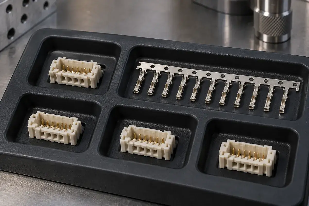
Packaging is the last restraint change before delivery. A tray that pushes a bowed component into a flat pocket can hide the condition until the customer removes it. Confirm that the packaging protects the contacts without becoming an unrecorded forming operation. If a controlled post-mold operation is necessary, document and validate it as a process step rather than relying on storage pressure.
For insert-molded connector components, include the carrier-removal state in the manufacturing review from the start. Our insert molding process overview provides the broader route. A well-defined release and inspection sequence turns cutoff from an afterthought into a measurable part of the component's dimensional control.