
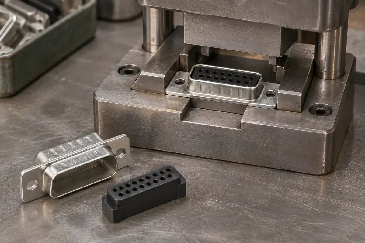
Damage found after a D-sub shell is closed is often blamed on a weak plastic insert. The insert may indeed need a geometry or material review, but first follow the assembly load. A shell that is incorrectly seated, a tool that reacts against the wrong surface or an obstructed contact can concentrate force where the molded component was never intended to carry it.
Shell crimping or tab forming is also distinct from crimping a wire to a contact. Here the operation secures the connector's metal enclosure around its internal components. Not every D-sub design uses the same closure method, so begin with the selected shell construction and its controlled assembly requirements rather than a generic press setting.
Product design illustrations accompany the component and assembly explanations below.
Confirm that the insert is seated before forming the shell
The plastic insert should reach the intended location within the shell under the conditions defined by the design. Identify the seating shoulders, orientation features and any parts captured between them. A perimeter that appears flush from one direction can hide a tilted insert or an obstruction at the opposite side.
Contacts can contribute to that obstruction. A contact that is not fully installed may prevent an insulating component from seating or may react against the assembly fixture. Inspect the loaded state before closure. Increasing forming force to eliminate an unexplained gap can turn a contact-loading problem into permanent damage to both the shell and the plastic.
A split insert introduces another seating relationship. The front and rear pieces must reach the specified assembled condition before, or as part of, the designed shell-closing sequence. The article on split-insulator alignment explains why individual component dimensions do not by themselves establish a correctly assembled pair.
Keep the shell and insert revisions together during evaluation. A small change to a retaining tab, formed lip or seating step can alter the point where load enters the plastic. A sample assembled with an earlier shell is not a complete check of a later closure feature, even if the external connector envelope has not changed.
Trace the reaction force through the tooling
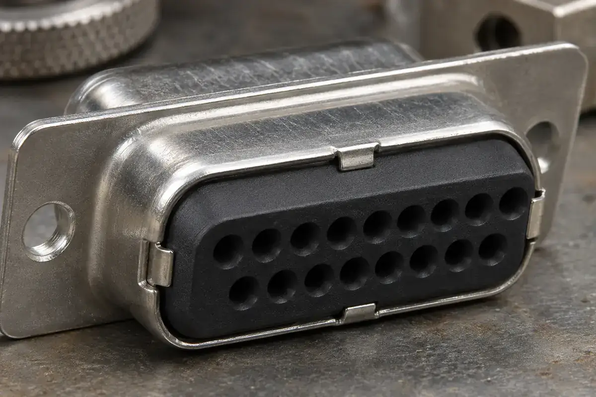
The forming tool applies force to the metal, but that force must return through a support. Ideally the support arrangement follows the intended shell assembly construction. If a narrow plastic edge becomes the unintended reaction point, the same press motion can create indentation, bending or cracking even when the metal feature appears properly formed.
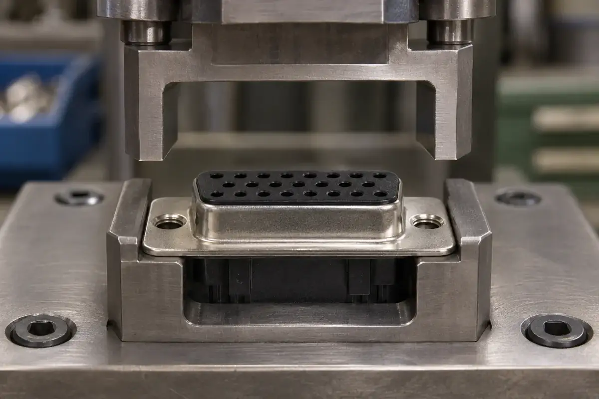
Review the tool and nest together in section. Show where the shell is supported, which surface the forming tool contacts and where the plastic sits relative to both. A broad tool face does not guarantee a broad load path if the component underneath is resting on only one small step or on a projecting contact.
Tool clearance matters as the metal changes shape. A forming feature can approach the insulator differently at the start and end of the stroke. Examine the whole travel and the final envelope, including any springback allowed by the process. The finished tab should retain the intended assembly without becoming an uncontrolled cutting or scraping edge against the plastic.
Use the manufacturer's defined assembly information for a catalogued shell. Product families such as Amphenol's D-sub range include different mechanical and termination options; the shared name does not establish one universal shell-closing method. For a custom shell, establish its process window through the agreed development work rather than copying a setting from another size.
Read the damage pattern before changing the resin
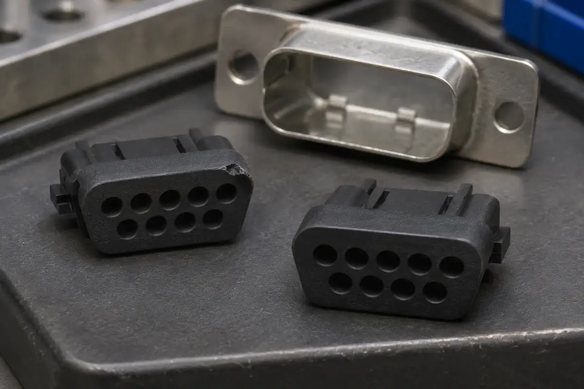
A localized mark directly beneath a retaining feature suggests a different investigation from a crack extending across a thin wall between contacts. Map the location relative to the shell and tooling. Consistent damage at one side can indicate seating or alignment, while variation across positions may point toward a different component or process interaction.
Separate cosmetic witness marks from functional damage using agreed acceptance criteria. A shallow outer impression may have different consequences from a crack reaching a contact-support surface. Conversely, a small-looking internal displacement can matter even when the exterior is tidy. The inspection method should expose the relevant function rather than relying only on how conspicuous the mark appears.
Material condition remains part of the review, but it should be identified rather than guessed from color. Confirm the exact molded grade and the handling or conditioning state specified for assembly. If a material change is proposed, evaluate its effect on the entire joint and molding process instead of assuming that a higher nominal strength solves an incorrect reaction force.
Compare the part before and after shell closure using the same references. This can reveal whether a dimensional error was already present or was introduced during the operation. Keep the observations tied to identified components and settings so that a later trial isolates the change being evaluated rather than mixing several possible causes.
Approve the closed assembly, not just the visible tab
A formed shell feature can look consistent while the contact pattern has moved. Include the relevant assembled locations in the acceptance plan: insert seating, contact projection or entry, and the relationship to the mating shell. The connector inspection-datum discussion provides a framework for connecting those observations to functional references.
Where retention or mating requirements apply, evaluate them using the agreed assembly and method. A visual check of shell closure does not establish a retention force or an electrical result. Keep the measured outcomes distinct from the process settings used to create the sample, and document the component revisions that were actually evaluated.
For repeat production, control the shell, molded insert, contacts and forming tooling as a connected configuration. Changes to any one of them may justify revisiting the closure operation. A clear record of the approved seating condition and support arrangement makes that review more useful than simply carrying forward the same machine setting.
When requesting custom D-sub insulators, include the shell-retention section and the planned closing sequence. This lets the molding review address solid support lands, delicate edges and inspection access early. Protecting the plastic begins with a defined assembly load path, and then with a component designed and molded to work within it.