
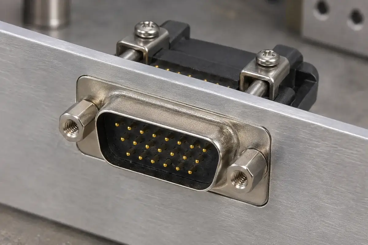
A D-sub connector that mates freely on the bench can become difficult to join after it is fastened into equipment. The panel, mounting ears and locking hardware have added another locating system. If that system moves the shell away from the intended mating axis, tightening the screws can force the contacts and plastic insulator to absorb a mismatch they were not designed to correct.
The useful investigation treats mounting and mating as related interfaces. Identify what positions each connector in the equipment, what guides the initial approach and what the jackscrews do after engagement begins. A locking screw can secure the connection without being a suitable tool for pulling two misaligned connector halves into position.
Product design illustrations accompany the component and assembly explanations below.
Define the mounting stack around the metal shell
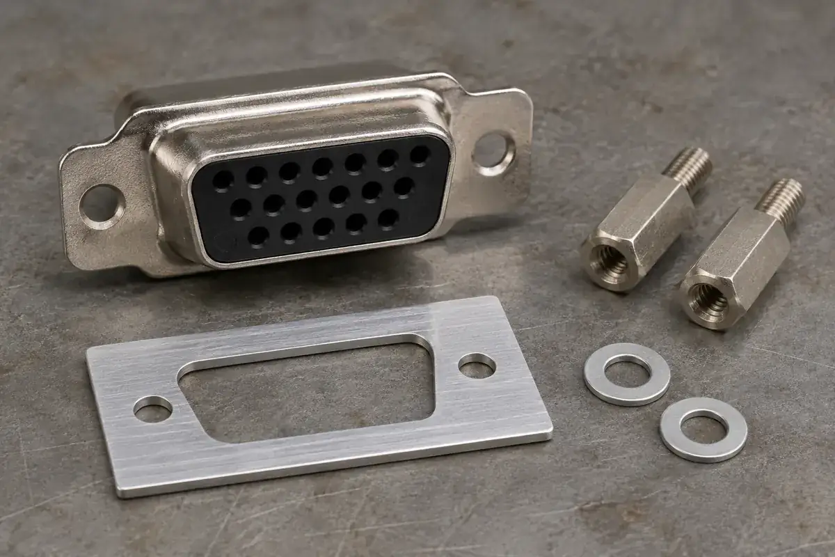
List the physical parts between the mounting ear and its support: panel, standoff, washer, bracket or other specified hardware. Their order affects the shell's installed position. A detail that looks like a simple fastener choice can change the mating-face setback or the distance between the connector and the surrounding equipment surface.
Use the actual mounting drawing rather than an assumed D-sub hardware pattern. HARTING's solder-cup connector information, for example, identifies its flange arrangement separately from contact and termination details. That illustrates why mounting features belong in the selected configuration, not in a generic note attached after the insulator has been designed.
The panel cutout needs to clear the intended part of the shell while supporting the specified flange region. If the cutout contacts an unintended surface, fastening can tilt the connector or hold it away from its seat. Check the installed section through the panel rather than only the face outline and the distance between mounting holes.
Consider the support on both sides. A thin panel can respond differently from a rigid bracket under the same assembly operation. The design should identify where the hardware bears and how the support behaves in the intended equipment. A washer can distribute load locally, but it does not automatically correct a poorly located or flexible mounting surface.
Keep locking action separate from alignment correction
At the start of mating, the connector pair should approach within its intended alignment conditions. The shell and any specified guidance features establish the engagement path. If the locking screw engages while the mating parts are still offset, its axial force may conceal the mismatch until contacts bend, the shell binds or the insulator is displaced.
Observe the assembly before the screws are tightened. A useful check is whether the shell reaches its expected engagement state under the defined installation method, without using hardware to overcome an unexplained obstruction. The acceptance criterion must come from the actual design; a general instruction to tighten until it fits is not a controlled mating method.
Different mounting arrangements intentionally provide different freedom. Some designs use a rigid location, while others include a specified floating feature to accommodate installation variation. Preserve that distinction in the drawing and hardware selection. Adding extra clearance to a fixed design is not automatically equivalent to a properly defined floating mount.
Fastening sequence can also matter when two side locations are involved. Uneven closure can rotate the shell or load one side first. Use the specified process for the selected assembly, and investigate a recurring need for correction. A custom insulator should not be asked to compensate for an equipment interface that consistently presents the connector at the wrong angle.
Relate the insulator to the mounted shell
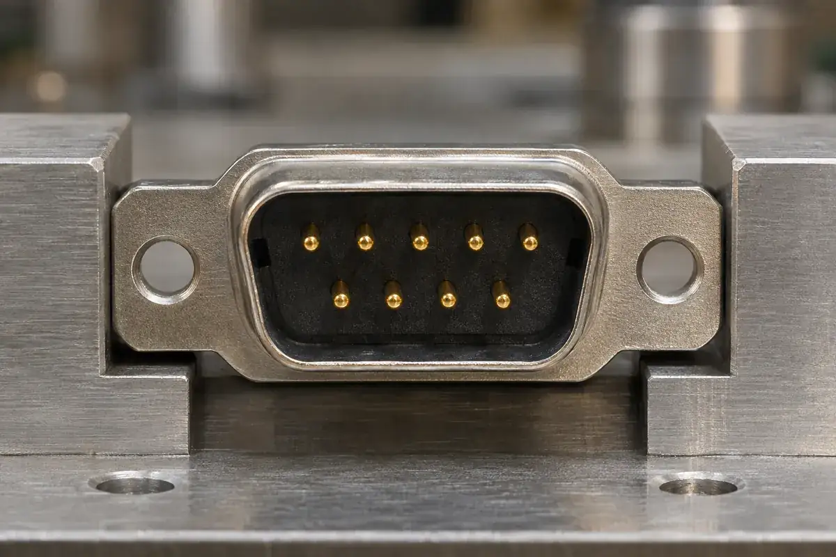
The contact pattern is positioned through a chain of interfaces: contacts within the plastic, plastic within the shell, and shell within the equipment. Each link has a defined role. Measuring the contact spacing alone does not reveal whether the entire pattern is correctly located relative to the mounting ears or the final equipment datum.
The insulator's seating features should therefore be reviewed together with the shell references used during installation. A molded body can fit the shell perimeter while allowing a different axial position or tilt than intended. Inspect the relevant support faces and the assembled contact position rather than using a cosmetic perimeter fit as the only acceptance check.
During diagnosis, compare the free connector pair with the mounted pair using the same known components. If the problem appears only after panel installation, that observation helps direct the review toward mounting and support. It does not prove that the plastic is correct, but it prevents an immediate and potentially misleading change to every contact cavity.
Our connector datum guide explains how to connect a hole pattern to functional references. For the mounted D-sub assembly, extend that reasoning to the shell and panel. The reported dimensions should make it possible to trace the contact location back to the interface that positions the connector in service.
Include the mounting configuration in the quotation and trial
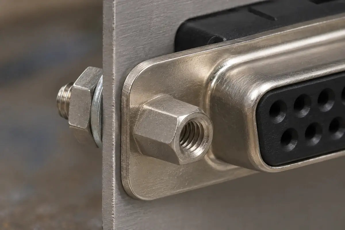
Provide the panel section, hardware arrangement and mating counterpart with the plastic drawing. Explain whether the supplier is quoting only the molded insert or additional assembly operations. The mounting hardware can remain outside the supply scope while still being essential reference information for evaluating the component's functional position.
Use the relevant installation state during sample review. A bench check can confirm some features, while the final bracket or panel exposes others. Keep those results separate and identify the support configuration used for each. A successful free-mating observation should not be presented as proof that every equipment installation will behave identically.
Also consider loads arriving from the cable or rear enclosure. The article on D-sub backshell strain relief follows how external cable forces can reach the contact area. Mounting and cable support should work together so that the insulator is not carrying unintended loads from two different directions.
For custom D-sub insulating components, define the contacts, shell seating and installed references as one interface package. This gives molding and inspection a clear target while leaving the mounting hardware responsible for its intended job. The result is a more useful design review than treating difficult installation as a problem to solve by tightening harder.