
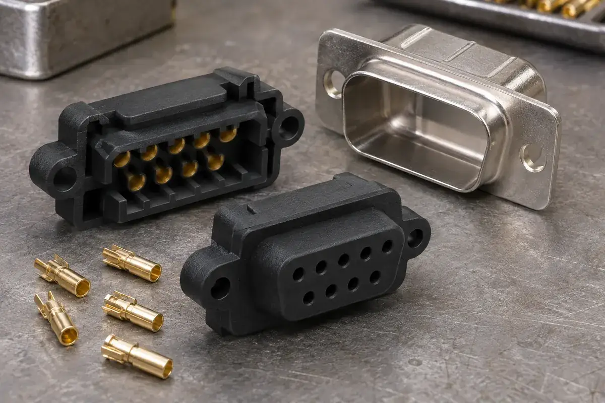
When a D-sub design uses separate front and rear insulating pieces, the joint becomes another functional interface. Each half can meet its own dimensions while the assembled contact pattern is displaced, pinched or incompletely seated. The useful question is not simply whether the two plastic outlines match, but how the halves locate one another while supporting the contacts.
A split construction may suit the chosen contact capture or assembly process, but it introduces additional handling and inspection decisions. Define those decisions before designing the mold. The contact geometry, shell seating and order of assembly determine which surfaces need to locate accurately and which should provide clearance rather than competing for control.
Product design illustrations accompany the component and assembly explanations below.
Give each locating feature a clear job
Start by identifying the surfaces that establish the position of the front half and the rear half. The front piece may locate from the shell or a fixture, while the rear piece locates from defined features on the front. The actual arrangement can differ, but the drawing should make the controlling relationship explicit instead of relying on several vaguely matching perimeters.
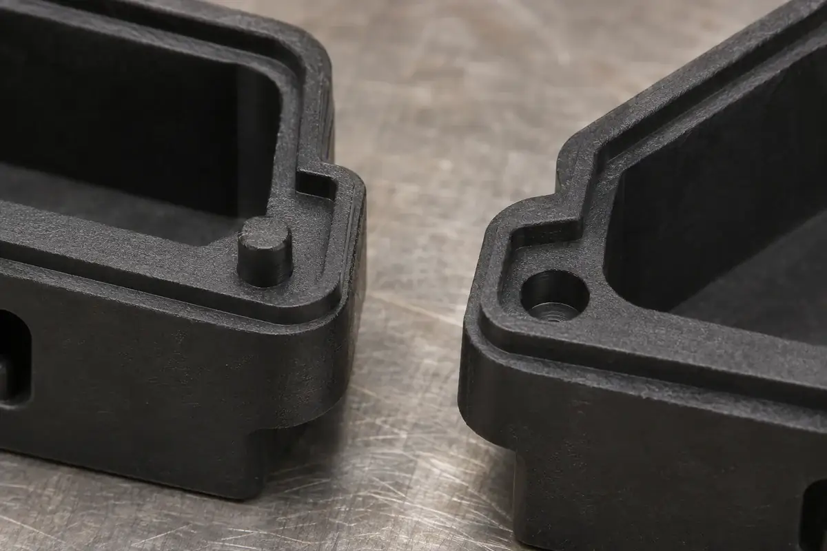
A boss and recess can guide the halves together, yet their fit needs to be considered with the rest of the joint. If the outside profile and multiple internal features all attempt to locate tightly at the same time, ordinary variation can create an assembly conflict. Decide which features establish position and where accommodation is intentionally allowed.
Orientation deserves separate attention. Similar front and rear outlines can permit an incorrect approach before the contact features reveal the mistake. A physical asymmetry can make the intended orientation easier to recognize, provided it is visible during the actual loading operation. A hidden key that becomes useful only after contacts are bent is too late in the sequence.
The related article on mating and wiring views explains how a correct pattern can become mirrored in documentation. Use those same orientation references for the split joint. The front and rear drawings should show how they relate in the assembled state, including the direction from which each component is viewed.
Capture the contact without creating an unintended clamp
A contact shoulder may be retained between the insulating pieces, or one half may provide the primary seat while the other guides a different region. The section drawing should identify the actual construction. Do not infer that pressing the halves tightly together is always the correct way to secure the metal part.
If the joint closes around a contact feature, compare that feature with the available cavity space through the full dimensional chain. A gap caused by an incorrectly seated contact can look like a plastic fit problem. Extra assembly force may then damage the joint while leaving the real obstruction unresolved inside the insulator.
The receiving contact's working region may require freedom even when its retention shoulder is fixed. Separate these regions in the cavity definition. The article on pin and socket cavity design describes why location, retention and mating action cannot be treated as the same requirement.
Contact-loading order affects access to the joint. A fixture can support the first half and keep loose contacts aligned while the second half approaches. Review where the fixture reacts assembly force and whether it clears the projecting contact ends. Supporting only a narrow perimeter can make an otherwise reasonable joint difficult to assemble consistently.
Connect the plastic joint to the shell assembly
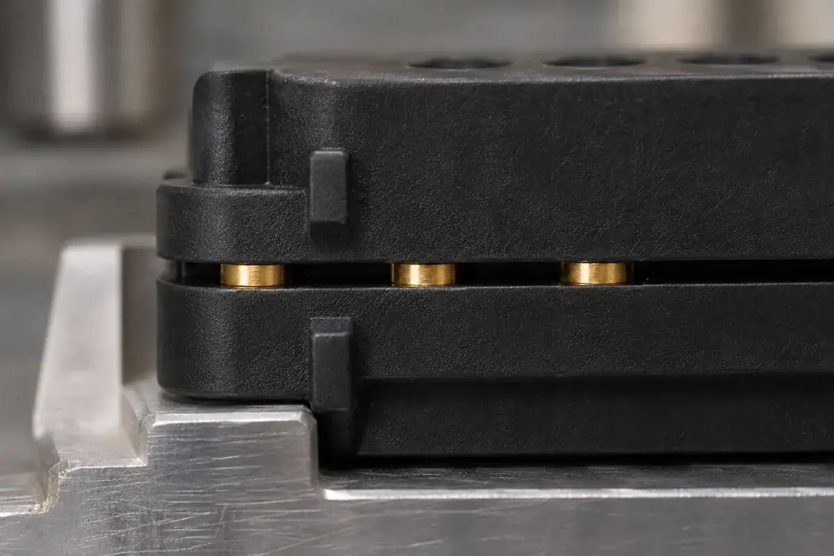
The metal shell may secure the completed insert, locate it, or perform both roles through different surfaces. Define the seating condition before the shell is closed or fastened. If the shell is expected to bring a partially assembled insert into its final state, that operation needs an explicit design and process review rather than an assumption that the metal will correct a loose joint.
Shell closure can add deformation and load around the perimeter. A plastic step or joint line placed directly under a retaining feature may be affected differently from a broad solid seating land. Review the full section through the shell and both halves to see where force travels during assembly and where it remains afterward.
Product families demonstrate that termination and assembly construction are specific choices. HARTING's D-sub cable-connector catalogue distinguishes crimp and solder termination arrangements. Use the selected series documents and your own component drawings to define the construction; a split insulator should not be presented as universal to all D-sub products.
For a new custom design, evaluate shell engagement with representative contacts installed. An empty plastic pair may close freely while the loaded pair does not. Keep the observed states separate so that a later change to contact seating, joint features or shell tooling is based on the interface that actually produced the problem.
Define acceptance for the assembled state
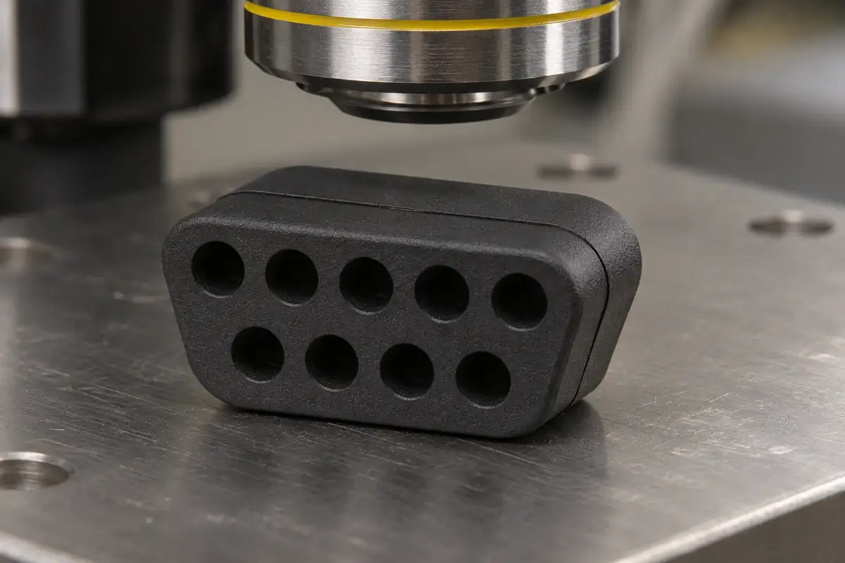
A joint line is not automatically a defect, and a visually closed line is not proof of correct assembly. State the permitted joint condition and the functional requirements it supports. Depending on the design, contact location or shell seating may be more informative than a cosmetic assessment of the perimeter alone.
Measure the loose halves from references that connect to their assembled function, then verify the result after contact loading. Record the component revisions and process used. This makes it possible to distinguish a cavity-location problem from an installation problem instead of repeatedly adjusting both halves to compensate for an unknown source of variation.
Material changes should be evaluated at the joint as well as at the individual part. Different molding shrinkage, stiffness or conditioning response can affect how the halves approach and seat. A color-matched substitute is not sufficient evidence that a previously approved joint will behave in the same way with the same contacts and shell.
For custom D-sub insulator components, include the assembled section, contact-loading sequence and shell interface with the separate plastic drawings. The mold review can then address the locating features, cavity access and support lands together. A clear joint definition turns a two-part insert into a controlled assembly rather than two independently acceptable pieces.