
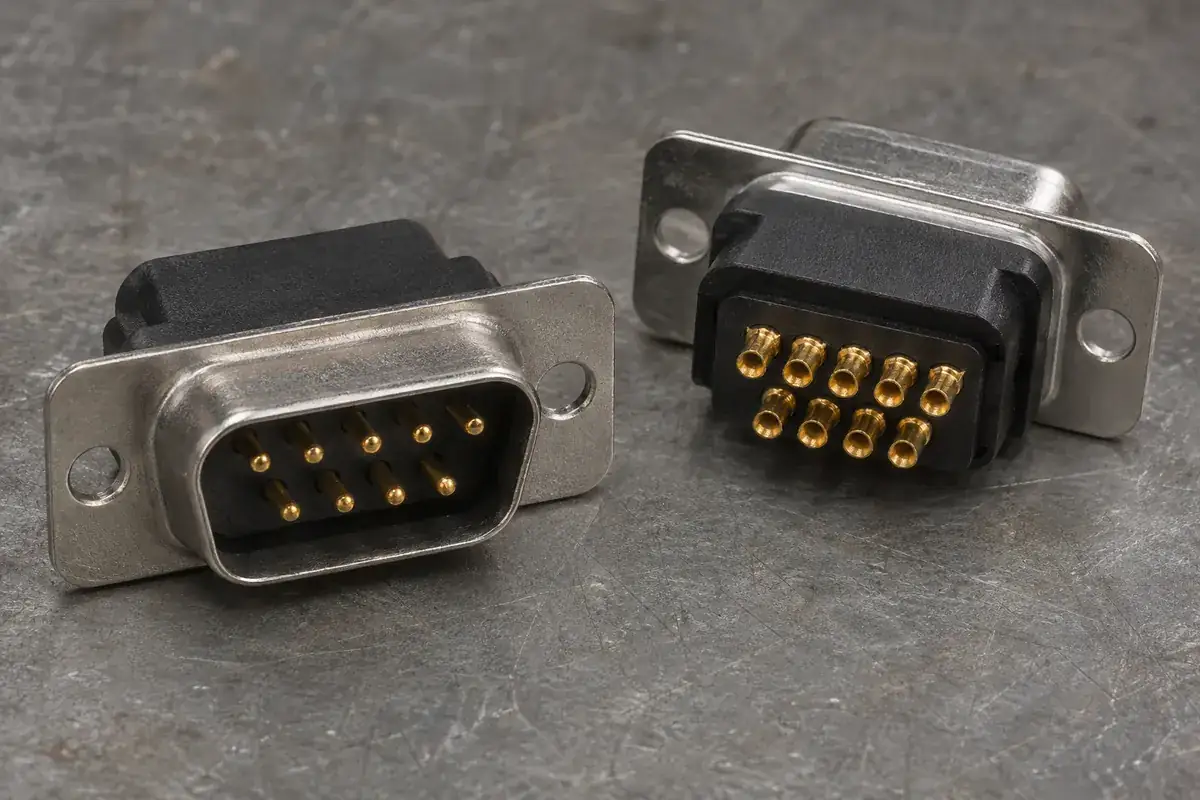
A D-sub drawing can contain the correct number of holes in a familiar outline and still communicate the wrong assembly. The common problem is viewpoint. A person looking into the mating face and a person looking at the wiring side see the same physical positions from opposite directions. Copying the visible left-to-right order between those views can mirror the intended layout.
This is not solved by adding more dimensions to an unlabeled picture. The drawing needs to state which face is being viewed, how the part is oriented and what identifies a physical position. Those references should remain consistent through the plastic model, contact drawing, wiring instruction and fixture used during assembly.
Product design illustrations accompany the component and assembly explanations below.
Establish the viewing direction before assigning positions
Begin with an explicit mating-face view and a separate rear or wiring-face view when both are needed. State the viewing direction in words, and show the D-shaped outline in its intended orientation. A drawing title such as front view is less helpful if different teams use front to mean the equipment exterior, the contact-entry side or the operator's workstation.
Turning a part around changes the apparent arrangement in a way that depends on how it was turned. Rotating it in the plane of the page is not the same operation as looking from the opposite side. Use the three-dimensional model or controlled section to derive the second view, rather than recreating the pattern by eye from a screenshot.
The shell outline can provide an orientation cue, but it should not be the only one. A small insert without its shell may look nearly symmetric during contact loading. A defined recess, notch or other physical reference can help tie the loose component to the drawing. That feature must be visible in the assembly state where it is expected to guide the operator.
Keep a reference view with the drawing revision that controls the mold. A picture copied from an older catalog variant can show a different gender or contact arrangement. The manufacturer drawing linked from a selected product, such as HARTING's solder-cup D-sub product information, is the appropriate place to resolve that product's mechanical view.
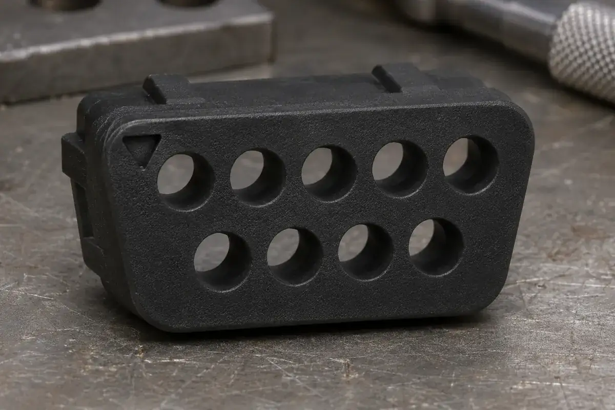
Separate cavity identity from the circuit assigned to it
A cavity identifier describes a physical location in the connector. The circuit connected to it belongs to the equipment design. A connector drawing should not rely on an assumed application pinout merely because the housing resembles a familiar interface. The same mechanical family may be used for different signals or for a custom connection schedule.
Provide the connection schedule as a controlled companion to the mechanical drawing. It should link each physical position to the correct conductor or circuit using the declared view. If a wiring instruction uses the rear view, make that explicit rather than forcing the assembler to mentally reverse a mating-face diagram at every termination.
For loose contacts, the loading order may differ from the logical circuit order. A rear-access position can become difficult to reach after neighboring wires are installed. The assembly instruction can choose a practical sequence while retaining the same cavity identities. Changing the order of operations should not silently renumber the molded part.
When there is a discrepancy, resolve it through a known reference pair rather than matching wire colors alone. Color conventions can vary between harnesses, and replacement wires may use a different marking system. The useful check follows an identified cavity through the connector and into the approved electrical connection, preserving the viewpoint throughout.
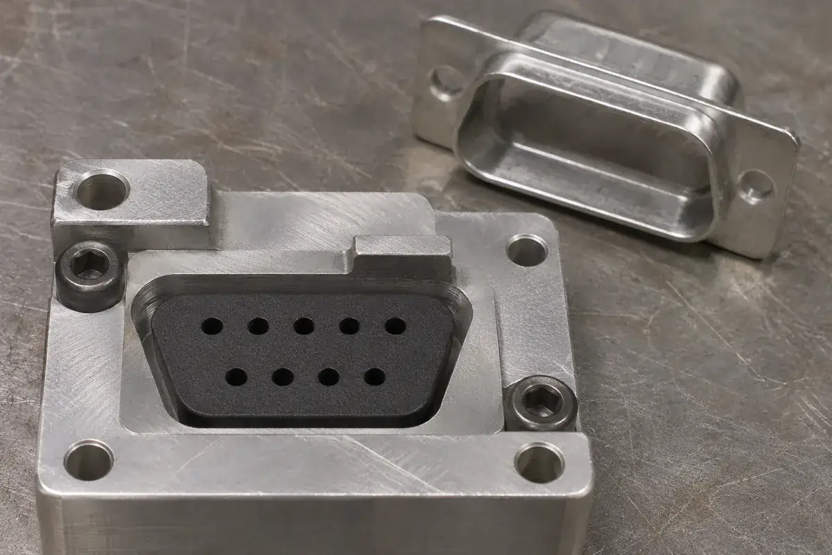
Carry orientation into molding, marking and inspection
The mold and the part drawing naturally involve additional views, including tool-facing directions and cavity layouts. Those are manufacturing references, not replacements for the released part view. A tool drawing may show a reversed pattern because it represents the surface that forms the part. The molded result must still be checked against the controlled component definition.
If molded position markings are required, verify them on the actual part-facing geometry before tool manufacture. A correctly located recess with a mirrored numeral is still an assembly problem. Specify the side from which the marking must be readable and whether it remains visible after the shell, contacts or backshell are installed.
Inspection programs need the same discipline. A measuring system can produce apparently regular hole coordinates while using an axis direction opposite to the drawing. Define the datum setup, orientation and reporting convention so a technician can relate a measured position to the physical cavity without an extra interpretation step.
The connector datum guide explains why a pattern must be related to its functional references. For a D-sub insert, include the orientation relationship as well as dimensional location. A symmetric measurement result can conceal an asymmetric marking or contact feature that has been placed on the wrong side.
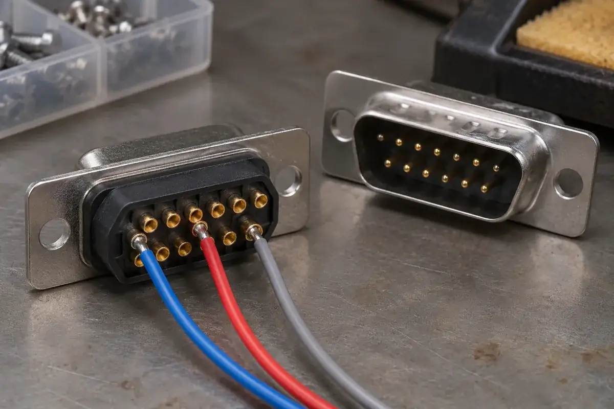
Review the complete handoff before releasing tooling
A useful review walks one physical cavity through every document: molded insert drawing, shell assembly, contact loading instruction and wiring schedule. Choose a position that is easy to identify from the orientation feature. Then repeat the check at a different part of the pattern to catch a reversal that a single central position would not reveal.
Include the actual gender and termination construction in that review. A male contact's visible pin tip and a female contact's entry opening describe different surfaces. The related article on pin and socket insulator holes explains why the same face-view pattern does not mean the underlying cavities can be copied unchanged.
Photographs can be useful supporting instructions when they show a known revision in a declared orientation. Keep them subordinate to the controlled definition, and replace them when the design changes. A mirrored presentation image or a rotated marketing photograph should never become the only authority for an assembly-critical location.
When requesting custom D-sub insulators, provide labeled mating and rear views alongside the three-dimensional model. This lets molding, contact loading and inspection work from the same physical references. The purpose is straightforward: make the intended part recognizable from either side without asking each downstream team to reconstruct the orientation.