
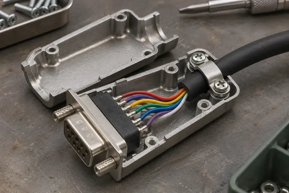
A neat cable bundle inside a D-sub backshell is not necessarily a protected termination. If a pull on the outer cable reaches the individual wires before it reaches the intended clamp or support, the contact terminations and their plastic seats can become part of the strain-relief system. That may remain hidden until handling or equipment installation changes the cable position.
The useful design question is where an external load travels. Follow it from the cable jacket through the clamp, backshell and mounting arrangement. Then examine the individual wires between the jacket end and the contacts. Their route should support the intended assembly without silently becoming the structure that holds the cable in place.
Product design illustrations accompany the component and assembly explanations below.
Define what the clamp actually grips
A cable clamp must be evaluated with the specified cable construction. Outer diameter, jacket material and shape influence how it sits against the support surfaces. A clamp that closes neatly around one cable may have a different contact condition around another, even when both assemblies contain the same number of conductors.
The intended gripping region is usually defined by the backshell and cable design, not chosen during final assembly to make the wires fit. Confirm whether the clamp is meant to engage the outer jacket and how the jacket is supported underneath. Do not place individual conductors under hardware intended for the complete cable unless that is an explicitly designed arrangement.
HARTING's D-sub cable-connector catalogue includes backshell and cable-support components alongside connector arrangements. Use the instructions for the selected system to define its assembly. The presence of a metal hood alone does not identify how strain relief or shielding is achieved in a particular configuration.
Where a clamp uses interchangeable inserts or support pieces, include the selected parts in the controlled bill of materials. An omitted insert can change the grip and the cable position without changing the outer appearance of the completed hood. The assembly instruction should make the internal configuration recognizable before the backshell is closed.
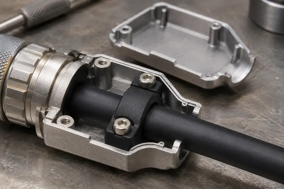
Leave a deliberate route between jacket and contacts
The jacket termination point determines where individual conductors begin to separate toward their contacts. If that point is too close to a crowded contact area, the wires may require abrupt changes in direction. If it is moved without considering the clamp, the intended gripping region may be lost. Review those two positions together in the assembled section.
Each wire should reach its termination without needing to pull the contact toward the cable exit. A small amount of routing allowance can accommodate assembly, but excessive loose length can become trapped when the hood closes. The appropriate route depends on wire construction, contact arrangement and available volume; it should be shown or otherwise defined for the actual assembly.
Check remote contact positions as well as those nearest the cable entry. A bundle can look relaxed overall while one individual wire is nearly straight and carries load first. That wire can move its terminal or load the surrounding plastic before the rest of the harness responds. Follow the routes individually during the design and sample review.
The D-sub solder-cup article discusses how termination sequence and tool access affect those routes. Similar questions apply to crimped or other contact systems, using their own assembly instructions. Strain-relief review should begin with correctly installed contacts, not be used to conceal a termination that is already under tension.
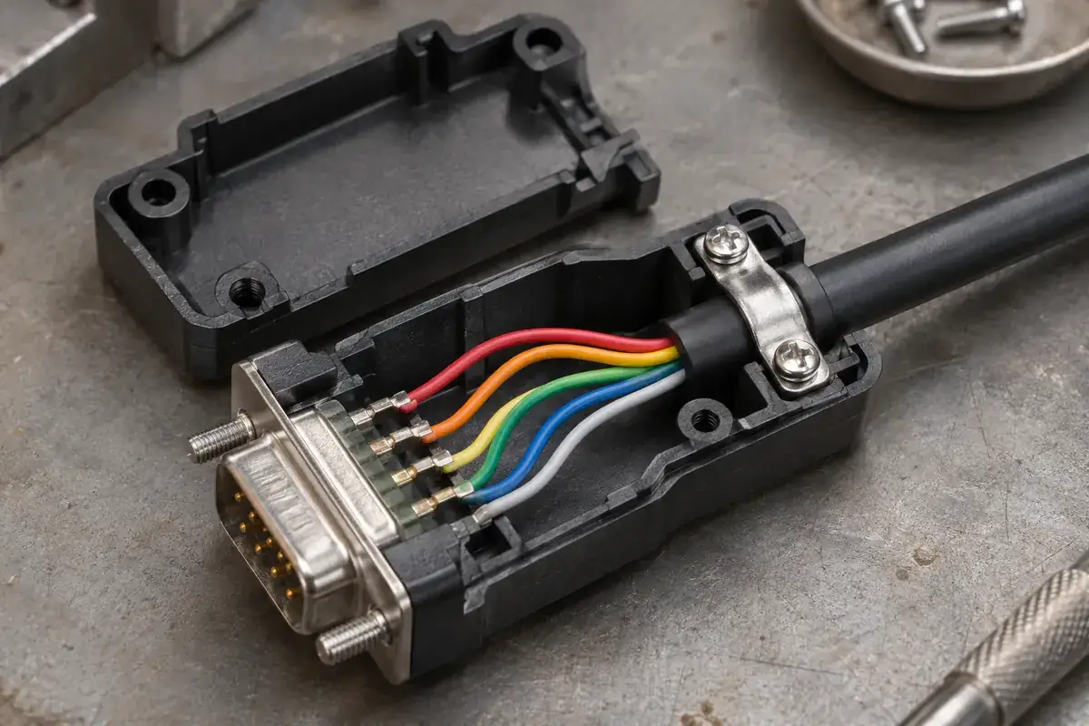
Connect the backshell to the connector mounting
Once the cable load reaches the backshell, it must continue through the intended mechanical connection. The hood attachment, connector shell and equipment mounting need to be considered as a system. A strong jacket clamp cannot protect the assembly if the resulting load is transferred through an unintended edge of the plastic insert.
The cable exit direction influences that loading. A straight exit and an angled exit can place different moments on the connector when the cable is routed through equipment. Include the actual installation envelope rather than testing only a cable lying freely on a bench. The required evaluation should reflect the specified use and handling conditions.
Mounting alignment also matters. If the connector is already being forced into position by its hardware, cable movement can add another load to an assembly under constraint. The article on jackscrews and flange alignment explains how to separate securing the connection from using screws to correct a mismatched installation.
Keep mechanical strain relief distinct from electrical shielding or environmental sealing. A component may contribute to more than one function, but those functions require their own defined interfaces and evidence. A conductive-looking hood or a tightly fitted clamp does not by appearance alone establish shield performance, ingress protection or a particular retention capability.
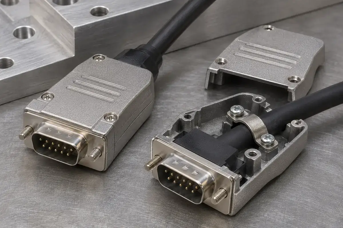
Evaluate the identified cable assembly
During sample review, observe the contacts and wire routes before the hood is closed, then evaluate the completed configuration using the agreed method. Record the cable, clamp inserts, backshell and connector revisions. These details make a measured result useful for the design under review instead of treating one successful sample as a property of every D-sub cable.
Acceptance criteria should identify the relevant outcomes and inspection state. Depending on the project, these may include cable movement, component condition or electrical checks after the specified exposure. A visible clamp impression is a process observation, not a substitute for the required performance result. Keep the observations and the acceptance decision distinct in the record.
For the molded insulator, review contact retention and support under the intended connector assembly conditions. If external cable force is reaching that component unexpectedly, address the strain-relief path before simply thickening the plastic. Extra material can change molding and contact access while leaving the original load-transfer problem unresolved.
When quoting custom D-sub insulators, include the cable termination and backshell arrangement as interface information even when the supply scope is plastic-only. This helps explain how the contact seats are used in service. A clear mechanical path gives each part a defined role and keeps routine cable handling from becoming an unintended test of the contact cavities.