
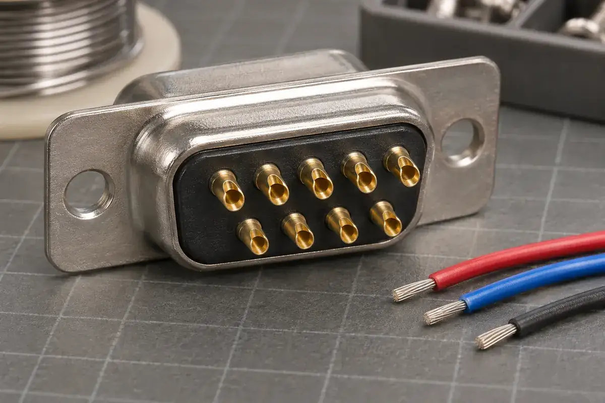
A D-sub solder cup can be easy to reach when the connector is empty and difficult to reach after half the wires have been installed. The contact pattern has not changed; the available working space has. Wire insulation, previously completed terminations and the assembly fixture now occupy the approach that looked clear in the original plastic model.
For a custom insulator, access should be reviewed as a sequence rather than a single empty view. Follow the selected wire from its preparation through termination and into the backshell. At each stage, identify what supports the contact, what the tool must reach and where the remaining wires can move without loading an already completed joint.
Product design illustrations accompany the component and assembly explanations below.
Start with the selected contact and wire
The solder cup belongs to a specific metal contact, with its own geometry and supported region inside the insulator. A nominal wire designation does not fully describe what occupies the rear space. Insulation diameter, conductor construction and any required termination protection affect the path into the cup and the clearance around neighboring positions.
HARTING's solder-cup D-sub product data specifies conductor and soldering-related information for that identified connector. Use the current instructions for the selected component. Do not transfer its limits to a custom contact or a different insulator merely because the two assemblies have the same number of positions.
Place the intended wire and contact models into the assembled section. Include the portion of insulation that approaches the termination and the space occupied by any sleeve or other specified protection. A view containing only a bare conductor can substantially overstate the working space available after the real wire is introduced.
Distinguish tool access from final routing space. A wire may fit comfortably after termination while blocking the approach needed to make the neighboring joint. The assembly sequence should account for both states. Changing the plastic cavity to create apparent space is unlikely to help if the obstruction is actually a previously installed wire crossing the tool path.
Use the assembly order to preserve working access
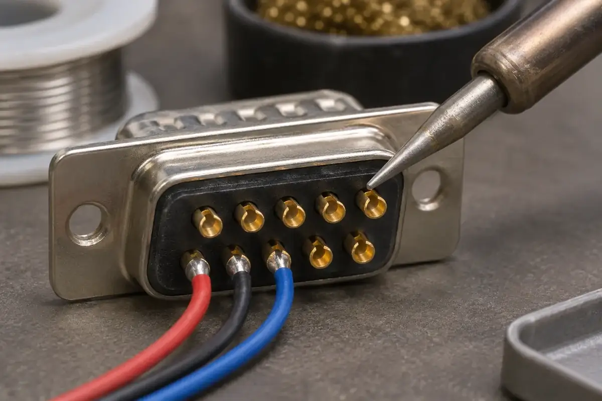
The best loading sequence depends on the particular contact pattern and workstation. Positions that become hidden by later wires may need to be completed earlier. Establish that sequence with the actual fixture and tooling, then connect it to the controlled cavity identities so a practical order of work does not create confusion about the required circuit connections.
Support the connector from appropriate surfaces while working at the rear. The fixture should hold the assembly steadily without reacting process loads through delicate pin tips or an unsupported plastic edge. It also needs to leave the intended tool approach available. A rigid fixture that blocks the rear row can force an awkward technique despite otherwise good component geometry.
Wire preparation and placement should follow the specified process. An excessively long exposed conductor can reduce separation from neighboring contacts, while a short or poorly routed end can encourage pulling on the wire during termination. Those conditions should be evaluated through the approved assembly instructions rather than compensated for by an informal change to the insert.
Thermal exposure belongs to the selected material and process review. The insulator must be considered in its actual assembled condition, including contact conduction paths and the permitted soldering operation. Avoid assigning a universal tool temperature or dwell time from the plastic family name alone; the manufacturer's component instructions and project evaluation define the applicable conditions.
Check the space after the backshell is added
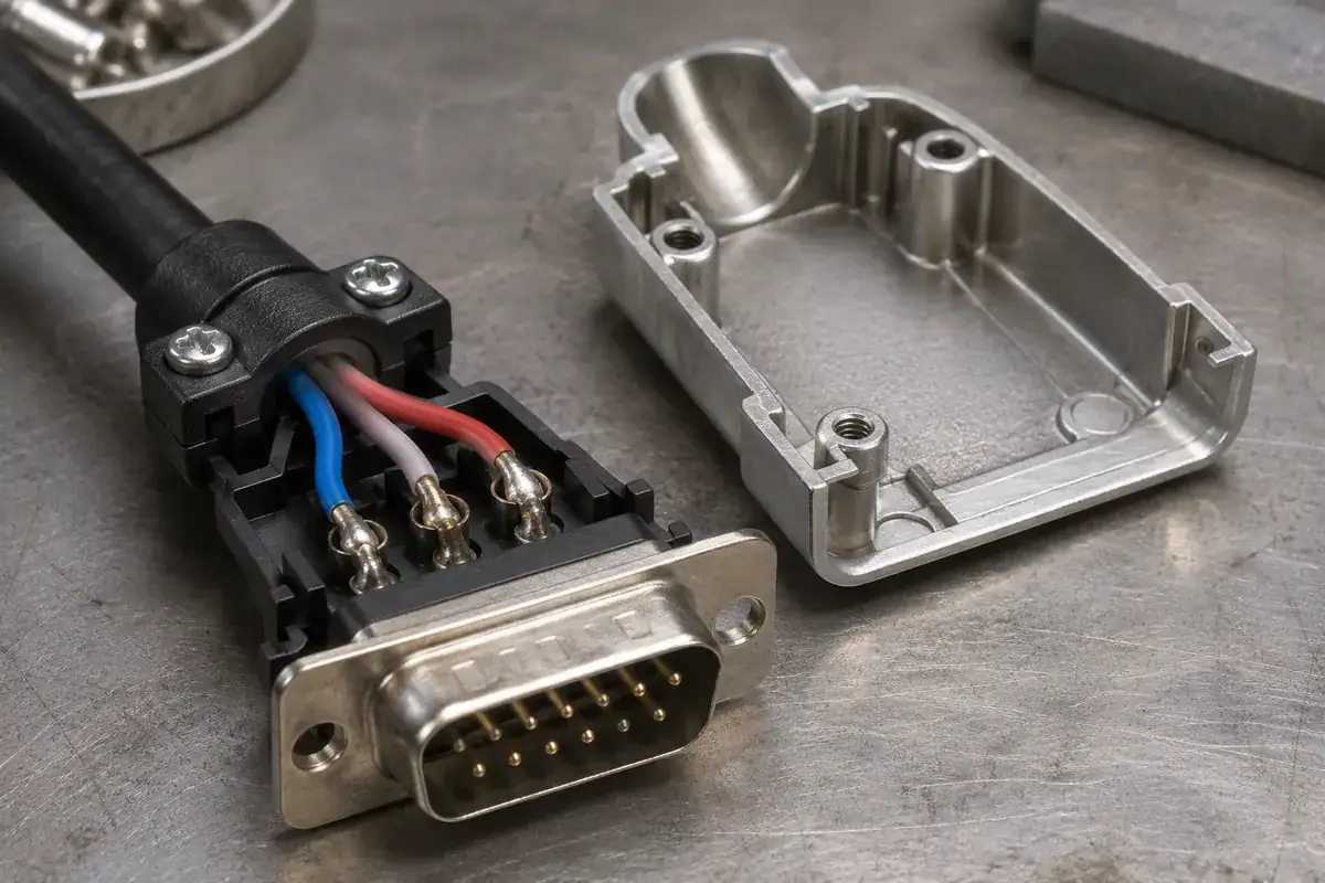
The backshell changes the available volume and may require the wire bundle to leave in a particular direction. Include it during the design review even if it is installed only after termination. A route that is convenient on the bench can become sharply folded or compressed when the enclosure halves close around the completed assembly.
Allow the individual wires to reach their contacts without becoming the primary support for the cable. The outer jacket and the specified strain-relief arrangement should handle the intended external cable load. The related backshell load-path article explains why a tidy bundle is not, by itself, a controlled strain-relief system.
Inspect the longest and shortest practical routes through the chosen contact pattern. The nearest cup to the cable entry may be easy to reach, while a remote position needs a different bend and more room. These differences can influence the assembly sequence and bundle arrangement even when every contact is nominally the same type.
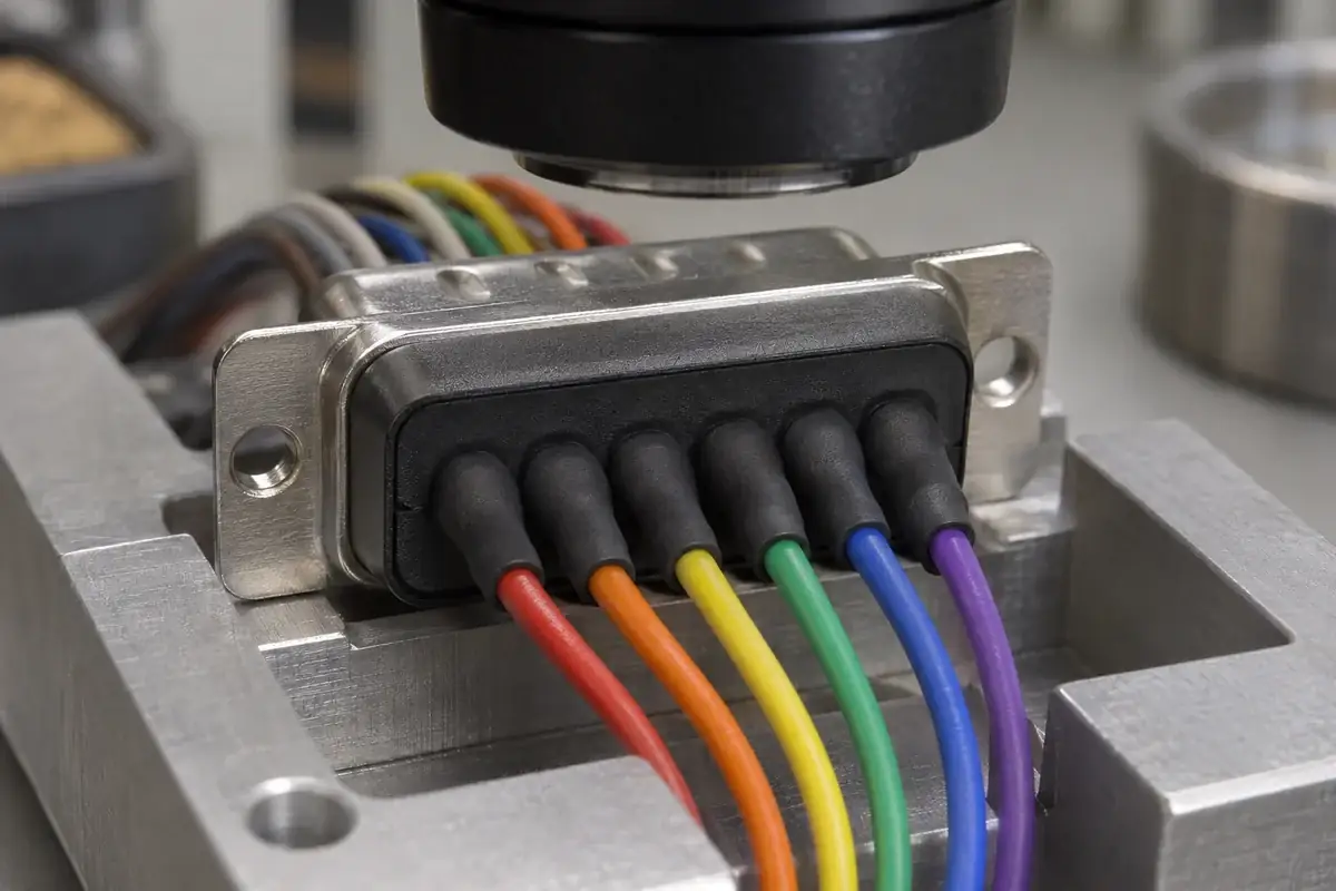
Where an insulating sleeve or other protective feature is specified, include its installed length and location in the space review. It can improve the intended separation while also increasing local stiffness or bulk. The appropriate choice follows the assembly requirements and evaluation, rather than an assumption that adding more material always improves the finished layout.
Define the molding features that matter to termination
The molded part should locate and retain the contacts according to their design while leaving the required rear access. Identify the surfaces near the cup where flash or other witness features could interfere with loading, protection or inspection. Functional zones deserve explicit drawing treatment rather than a general cosmetic statement covering every surface equally.
Do not create rear clearance by weakening the contact support without evaluating the consequence. A wall removed to improve tool access may also locate the contact or separate neighboring terminations. Consider whether a fixture, sequence or contact configuration change solves the access problem more effectively before changing the molded support region.
Use labeled mating and rear views to connect the manufacturing review to the wiring instruction. Our guide to D-sub drawing views describes the mirroring problem that can arise at this handoff. The correct contact must remain identifiable even when the connector is turned over in the assembly fixture.
For custom D-sub insulators, include the contact, wire, fixture approach and backshell arrangement with the plastic drawing. A useful review then covers the sequence from loose molded part to enclosed cable assembly. It addresses access where the work actually happens, rather than treating empty space in a rendering as proof of a practical termination process.