
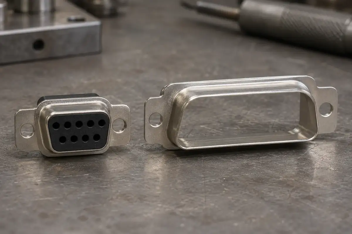
DB9 is a familiar purchasing term, but it can hide a disagreement about the connector being ordered. In the traditional D-sub shell-letter system, the common standard-density nine-position connector uses the E shell and is described as DE9. The B shell belongs to a different envelope. That distinction matters when a supplier is making the plastic insulator rather than simply searching a distributor catalogue.
The practical response is to preserve the customer's familiar search term while resolving the engineering definition. A quotation can mention the commonly used name, but the released drawing needs a controlled shell interface and contact arrangement. Correcting the letters alone does not establish the part: two people can agree on DE9 and still be describing different contact genders, rear terminations or mounting hardware.
Product design illustrations accompany the component and assembly explanations below.
Separate the shell designation from the number of contacts
A D-sub designation joins several decisions that are easy to blur together. The shell describes the mating envelope. The contact arrangement describes the populated positions within it. Gender identifies the receiving or projecting contact construction. A manufacturer's complete part number may then add termination, hardware and other options that are absent from the abbreviated family name.
Amphenol's D-sub overview lists shell letters separately from contact configurations, including E for the standard nine-position arrangement and B for the standard twenty-five-position arrangement. Use the selected manufacturer's drawing to resolve the actual interface; a colloquial name is a useful search aid rather than a sufficient manufacturing specification.
This is especially relevant when a project moves from an off-the-shelf assembly to a custom molded insert. The insert's perimeter must fit the selected shell, while its hole pattern must position the specified contacts. Copying a nine-hole pattern into a body taken from another shell size does not create a usable equivalent, even if both are loosely called D-sub components.
Start the comparison with the shell outline, mounting references and insulator seating surfaces. Then check the contact coordinates and their relationship to that outline. A photograph can help identify a likely family, but perspective and hidden features make it a poor substitute for the controlled dimensions that determine fit and retention.
Specify the contact system behind the familiar face
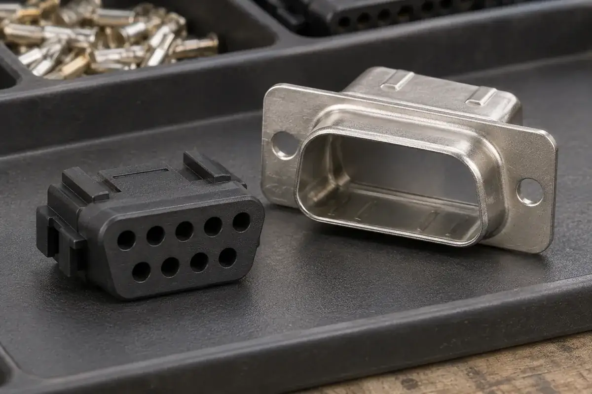
The mating face is only one end of a contact. A pin may continue into a solder cup, a board tail or another termination construction. The plastic around that contact must support its installation and its finished position. Changing the rear termination can alter cavity depth, the seating shoulder or the space required behind the insert.
The same abbreviated connector name also says little about whether contacts are supplied loose or already installed. A molded part intended for later contact loading needs a defined entry path and retention arrangement. A construction assembled around the contacts requires a different explanation of the manufacturing sequence. These decisions belong in the drawing package before the mold design is released.
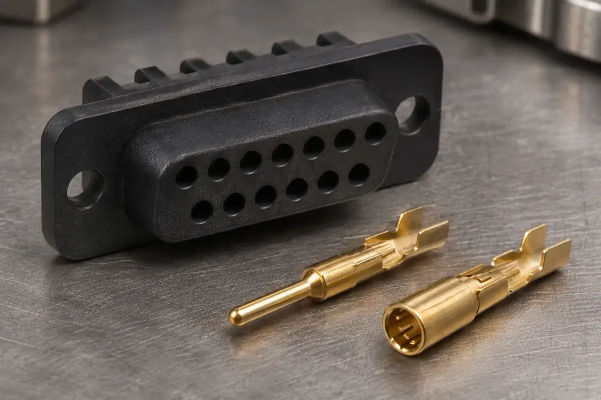
Gender should be written explicitly alongside the contact drawing. Terms such as plug and receptacle can describe a housing or an installation role, while the metal contact is unambiguously a pin or a socket. State which convention the project uses and include the mating counterpart so that a purchasing label cannot silently reverse the required cavity design.
For a custom quotation, separate what is being supplied from what is being referenced. The plastic insert may be the deliverable, while the shell and contacts are customer-supplied interface parts. Include their drawing revisions or approved samples. This gives the molding review a stable target without implying that the supplier is also supplying an entire connector system.
Make the drawing view and inspection reference explicit
A correctly named connector can still have a mirrored layout on its drawing. Label the mating face and the wiring face, and identify the orientation feature used in each view. Looking through the connector from behind changes the apparent left-to-right order. The hole coordinates and circuit identification need an intentional transformation between the two views.
Keep mechanical position identifiers distinct from circuit functions. A cavity number is a way to identify a physical location; the connected signal depends on the application. A DE9 shape alone does not define a universal wiring assignment. An assembly drawing should connect the physical position to the circuit requirement through an approved connection schedule.
Inspection references should follow the actual assembly. If the metal shell locates the insulator, the important question is where the contact pattern sits relative to the relevant seating features. Measuring only the distance between neighboring holes can miss a whole pattern shifted relative to the shell. Our guide to connector datums explains this distinction.
For a replacement component, compare the full interface rather than relying on a familiar name or matching color. Shell engagement, contact depth, retention and mounting arrangement all contribute to function. A custom part should be evaluated with the specified counterpart; an abbreviated description cannot establish interchangeability with every product sold under that term.
Turn the naming discussion into a clear purchase description
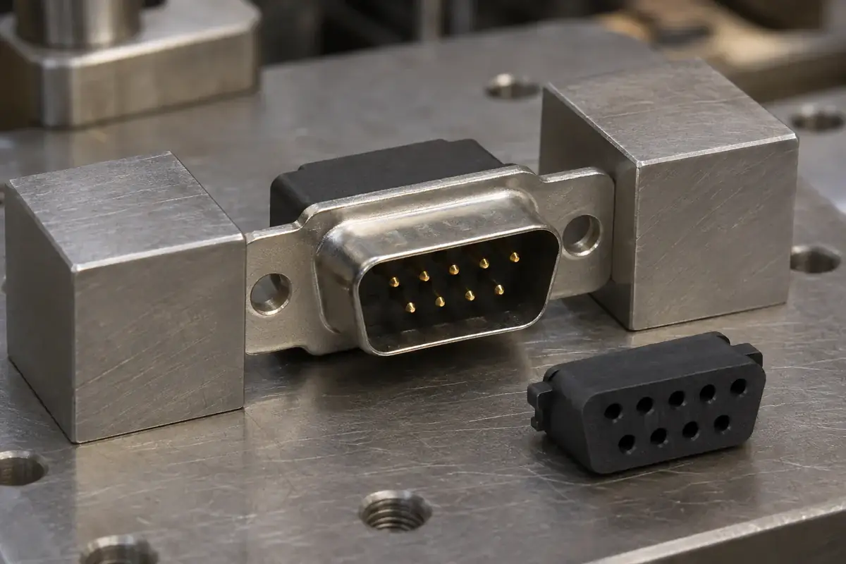
A useful description identifies a custom molded D-sub insulator, its shell interface, the contact arrangement and the controlled drawing revision. Add the material requirement and supply state. Put an informal alias in a separate search or reference field if it helps the buying team, rather than using it as the sole definition of the manufactured part.
Where the existing documentation conflicts, record the decision in one revised drawing package. A corrected email subject is easily separated from an old attachment. The model, drawing, contact reference and inspection plan should describe the same configuration so that tooling, sampling and repeat orders are not working from different versions of the connector.
The related comparison of standard and high-density insulators covers another naming trap: similar shell envelopes can contain different contact patterns. Resolve density separately from the shell designation and avoid treating a higher position count as a small change to an otherwise identical plastic insert.
For custom D-sub connector insulators, send the shell and contact references alongside the plastic drawing. With those interfaces established, the review can focus on core geometry, molding access, assembly and measurement. The familiar name then remains useful for communication without carrying more technical meaning than it actually provides.