
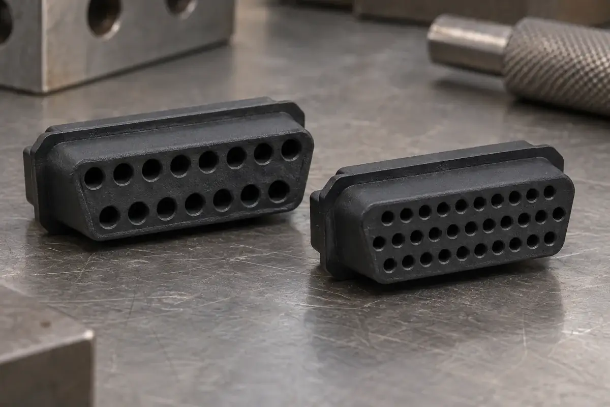
Two D-sub connectors can occupy similar panel space while asking very different things of their molded insulators. A denser contact arrangement changes the material between holes, the core pattern in the mold and the space available for contact loading. It also changes what can be reached behind the connector after wires or board terminations have been added.
The useful comparison therefore begins inside the familiar D-shaped envelope. Identify the actual contact arrangement and metal components, then follow their support and assembly requirements through the plastic. A high-density insert is a different interface design; reducing the spacing in a standard insert model without reviewing those relationships is an incomplete starting point.
Product design illustrations accompany the component and assembly explanations below.
Compare the actual arrangement within the shell
Density describes how contacts are arranged within an available envelope, but the family label alone does not define every dimension. Contact diameter, row spacing, stagger and the distance to the shell depend on the selected series. Use its drawing as the reference instead of constructing a pattern from an assumed number of rows and a remembered pitch.
Amphenol's high-density board-mount range describes increased contact capacity within basic shell sizes and offers different termination forms. That is a useful reminder that the front arrangement and the rear connection are related choices. A particular family description should not be extended into a universal dimension rule for custom parts.
Place the contact models into the insulator model before judging the remaining plastic. The visible hole at the mating face may be smaller than a hidden retention region or a loading feature farther inside. Those larger internal envelopes can determine the minimum wall between adjacent cavities even when the front face appears to have generous separation.
Also compare the edge positions. The outermost contacts may approach a sloping shell wall or a mounting feature differently from the middle contacts. A pattern that is regular on a coordinate table can produce different local support conditions around its perimeter. Review the whole insert rather than assuming that one central cavity represents every position.
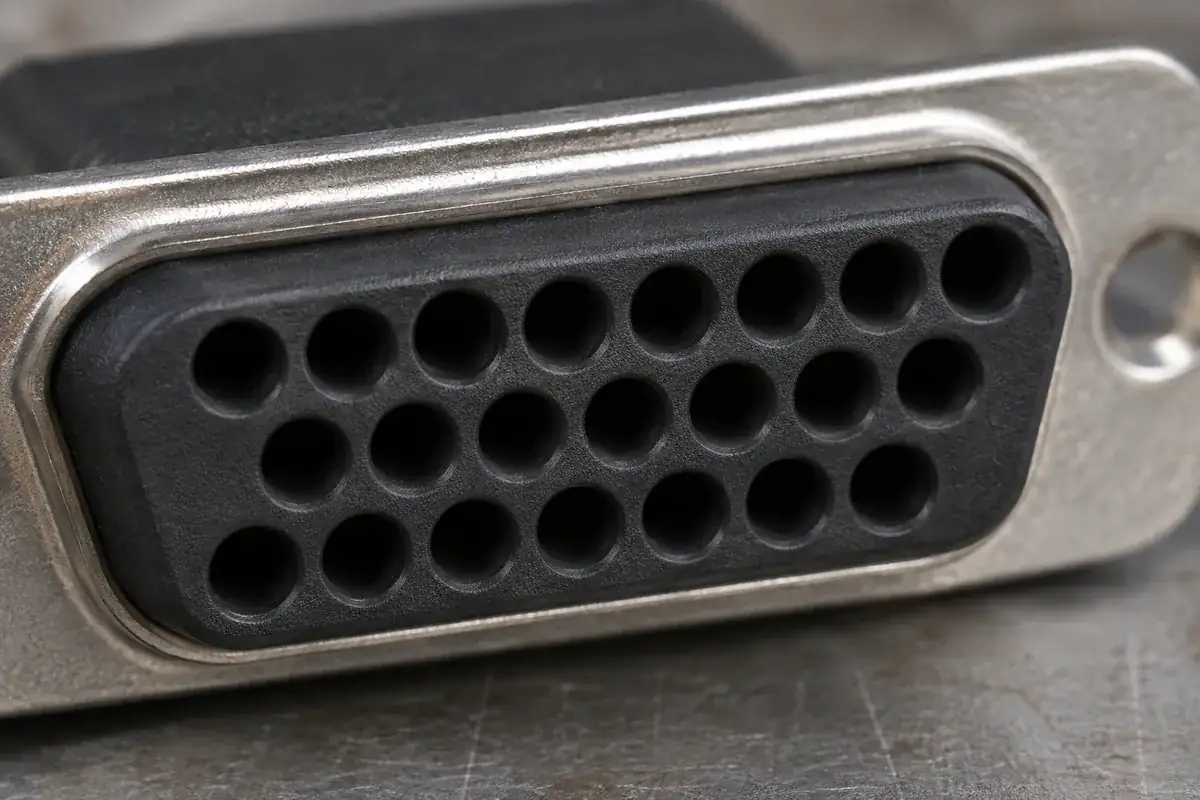
Follow thin webs into the molding process
Closely spaced openings create a dense core arrangement in the tool. Core size, unsupported length and access for manufacture or replacement deserve attention together. A small dimensional change in a contact cavity may affect the strength or arrangement of the tool steel, so the tooling review should use the functional cavity definition rather than a simplified cosmetic model.
Thin plastic webs also change the filling problem. Melt must reach the regions between the cores and join around them under the selected process conditions. Gate position, flow path and venting influence the resulting part. The right response is a geometry and process review, not an assumption that choosing a nominally stronger resin removes every molding concern.
Parting lines and flash allowances become important near narrow contact entrances. Small unwanted material can obstruct contact loading or affect the intended entry profile. Define which cavity surfaces are functional and where witness features are acceptable. This allows the tool designer to evaluate shutoffs and parting arrangements against the real installation path.
Ejection needs the same level of attention. Available solid lands can become scarce when much of the face is occupied by openings. Locate the intended ejection support and consider how the insert is released without distorting its pattern. A molded sample that looks complete should still be inspected from the agreed references after the specified conditioning state.
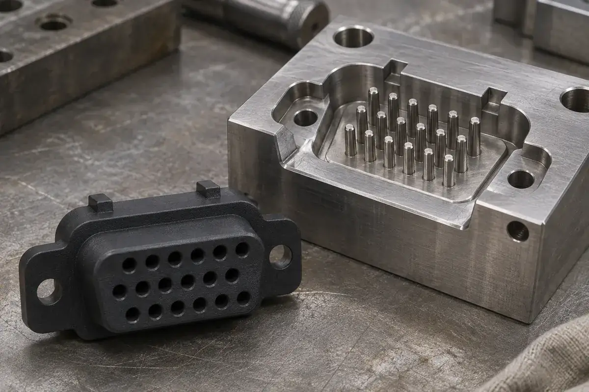
Check what happens behind the denser face
The rear termination can become the practical limitation before the mating face does. Wires, solder cups or board tails need room to be installed and inspected. The available space depends on the termination construction and assembly tools, not simply on whether all contact centers can be drawn inside the front outline.
For wired assemblies, consider the route from each contact to the cable bundle. A denser rear pattern may need a more deliberate loading or soldering sequence to keep later positions accessible. The wire insulation and any termination protection take up space that is absent from a model containing only bare metal contacts.
For board-mounted versions, include the board interface and the assembly direction in the review. A front contact pattern does not necessarily map directly onto the rear tail pattern. The contact's formed geometry can redistribute that pattern. The plastic needs to support the actual transition while leaving space for the selected board installation process.
Mechanical fastening should also remain accessible. Mounting ears, jackscrews and backshell features can limit tool approach around a packed contact arrangement. Consider the final equipment installation as well as bench assembly. Our discussion of solder-cup access follows one example of this rear-side constraint in more detail.
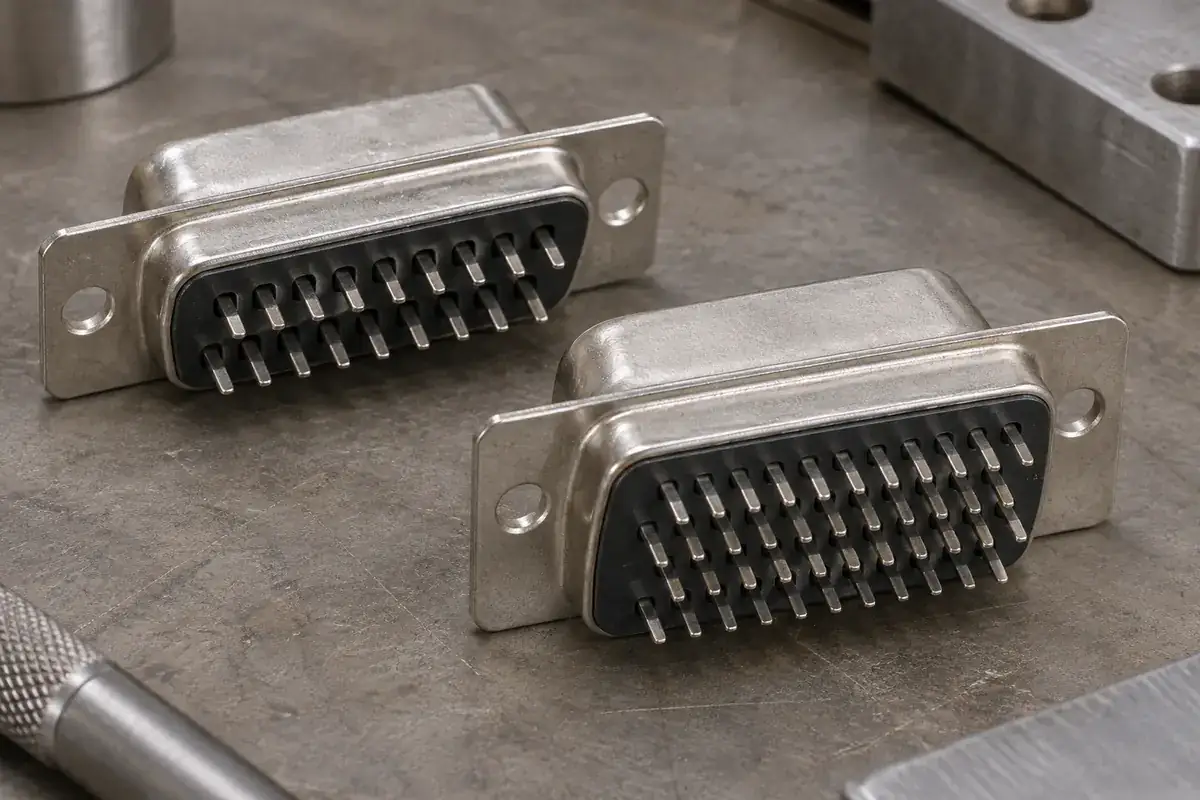
Specify performance through the identified assembly
Neither a higher density nor a familiar shell shape assigns an electrical rating to a custom insert. Insulating paths, the exact material, contacts, operating conditions and applicable evaluation method must be defined for the assembly. Manufacturer ratings for a complete catalogued connector should not be copied onto an unrelated molded component.
The sample plan should separate empty-insert measurements from assembled checks. Inspect the cavity pattern and shell seating features on the plastic, then evaluate contact position after loading. A contact can introduce its own location variation or reveal a hidden cavity interference. Combining those observations helps identify which part of the assembly needs correction.
When comparing alternatives, hold the functional boundary constant. Include the same termination method, required contacts, mounting approach and evidence requirements. A lower molded-part price is not a complete comparison if one option creates additional contact-loading operations or needs a different rear enclosure. The D-sub naming guide helps keep the reference configurations explicit.
For custom D-sub insulating inserts, share the complete contact and shell arrangement with the plastic model. The resulting review can connect density to mold construction, assembly access and measurement. That is a more useful basis for a manufacturing decision than treating the extra positions as a simple increase in hole count.