
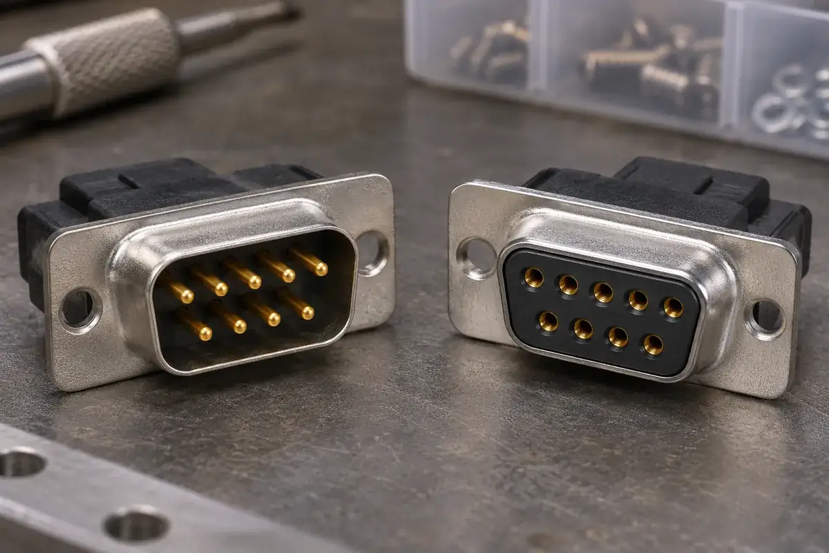
A pin and a socket can occupy matching positions across a D-sub mating interface without needing the same hole through their insulators. The projecting contact has one shape and support requirement; the receptacle has another. Treating both plastic parts as a shared pattern of simple cylindrical bores overlooks the shoulders, retention details and contact-entry regions inside the assembly.
The better starting point is a section through the actual metal contact in its installed state. Follow the contact from the mating end to the rear termination and identify every place where the plastic locates, retains or guides it. This separates a shared interface coordinate from the cavity geometry needed to support each contact construction.
Product design illustrations accompany the component and assembly explanations below.
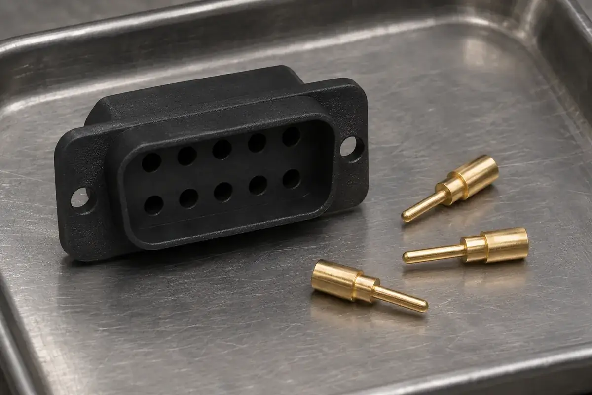
A pin cavity supports the specified metal profile
A male contact presents a projecting mating region, but the portion inside the insulator may include shoulders or other features that establish its installed position. Those features determine where the cavity changes shape. The slender mating tip alone is therefore not enough information for sizing the entire plastic opening.
Identify the contact-loading direction and the feature that stops further travel. A contact installed from the rear may need an entry path that differs from the mating-face opening. If the drawing simply gives one diameter through the body, the tool designer cannot reliably infer where the contact seats or how the assembly resists axial movement.
The contact must also remain oriented and supported as required by its termination. A round mating pin may continue into a shaped solder cup or board tail whose orientation matters behind the insert. A circular front hole does not automatically control that rear orientation. Review the complete metal profile and any separate feature used to establish its position.
Manufacturer families distinguish contact gender and termination as separate configuration information. Amphenol's D-sub range overview describes pin and socket arrangements alongside multiple termination forms. For a custom insulator, obtain the exact contact drawing rather than using the family name to fill in the hidden geometry.
A socket cavity must leave the receiving contact functional
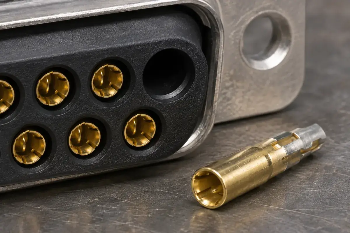
A receptacle contact includes a receiving region that interacts with the mating pin. Its outside envelope can differ from that of the corresponding male contact, and its working region may require space to act as intended. The plastic must locate the contact without unintentionally constraining a spring feature or moving the intended mating entry.
The opening at the plastic face and the entry into the metal receptacle should be considered together. The plastic may guide an approaching pin toward the contact, but an incorrectly located edge can become an obstruction. Evaluate the path of the actual pin through the assembled entry rather than judging the face opening independently.
A larger cavity is not automatically a safer cavity. Excessive freedom can allow a contact to tilt or shift away from its intended entry location. Conversely, reducing clearance around the entire receptacle may interfere with loading or contact function. Identify which region provides location and which region requires clearance before changing a core diameter.
Keep contact retention distinct from mating action. The metal receptacle may exert a force on the mating pin, while another feature keeps the receptacle inside the insulator. A successful electrical engagement does not prove that the terminal is correctly retained. The sample evaluation should observe the installed metal component as well as the mating pair.
Review molding access and the assembly sequence together
A stepped cavity can be straightforward or difficult to mold depending on the direction of its features. Identify the core withdrawal direction and any geometry that prevents a simple release. Tool construction should follow the functional cavity, while the functional design should be reviewed for practical mold manufacture and maintenance before dimensions are frozen.
Some assemblies use multiple insulating components to capture or support contacts. That can change which cavity details belong in each molded part. It does not mean that every D-sub insulator should be split. Compare the actual assembly sequence and retention method before adding a joint or converting a one-piece design into multiple pieces.
Small openings also need clear rules for flash and surface condition. A trace of excess material at a contact-loading shoulder may matter more than a visible witness on an unrelated outer face. Mark the functional entry and seating zones on the drawing so that tool shutoffs, inspection and acceptance all address the same surfaces.
The guide to split D-sub insulator alignment follows the additional locating relationship introduced by a two-piece construction. Whether the design is split or solid, document the point at which the contact becomes fully seated and the features that preserve that position during subsequent shell assembly.
Inspect the cavities and the assembled contact pattern
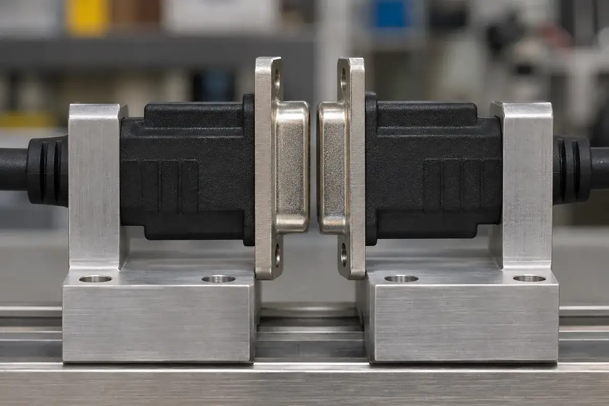
Inspection of the empty molded part should use the specified cavity sections and reference surfaces. An accessible front diameter may be easy to measure while a hidden shoulder controls the contact position. Decide how that shoulder will be checked, and avoid substituting a convenient measurement for the feature that determines the assembled result.
After loading contacts, check their resulting location relative to the shell interface and the mating reference. This distinguishes a molded cavity issue from a contact or installation issue. Use identified contact revisions and the planned assembly process; changing the metal specimen during the comparison can obscure the source of a difference.
Electrical and durability requirements belong to the defined connector assembly and its evaluation plan. Neither a cavity drawing nor a product design illustration establishes those results. The mating and wiring view guide also helps ensure that the measured position is the same physical cavity referenced by the assembly documentation.
For custom D-sub pin and socket insulators, submit both the plastic model and the complete contact geometry. Include loading direction, retention construction, final contact position and the mating counterpart. Those details make it possible to review the molded component as part of a functioning assembly rather than as an isolated array of holes.