
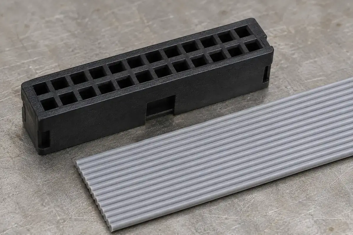
A ribbon-cable drawing and a connector drawing can show different pitch values without describing an incompatible pair. One dimension may locate adjacent conductors in the cable; another may describe contact centers at the mating face. Between those two interfaces, the metal contacts can follow a different arrangement. Reading every pitch as the same spacing is an easy way to specify the wrong plastic guide.
The useful starting point is a conductor-to-contact map. Follow one conductor from the cable into its termination slot and then to the mating position. Repeat that check at the edges and across the row transition. This establishes what the geometry means before anyone decides that a familiar nominal pitch is sufficient evidence of compatibility.
Product design illustrations accompany the assembly and manufacturing explanations below.
Identify which interface each dimension controls
Ribbon-cable conductor pitch describes the spacing between conductor centerlines along the flat cable. Overall width also includes the material beyond the outside conductors. Those two dimensions are related but not interchangeable. A cable can have the intended center spacing while its edge margins differ enough to change how it sits between molded side guides.
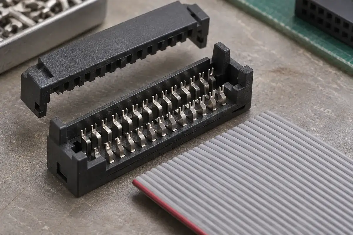
The contact pattern at an IDC termination may differ from the mating pattern. In some constructions, alternating conductors connect to different rows at the mating face. The plastic then has to locate the cable relative to the termination features, while the mating face is controlled by another set of contact and housing references. Both views belong in the assembly definition.
The 3M 891 Series drawing lists cable pitch separately from its two-row socket grid. That is a product-specific example, not a universal conversion rule. A different connector family can use another contact arrangement, cable type or numbering convention, even if its external body looks similar.
When reviewing a drawing, label the view and the interface before comparing dimensions. A top view of the cable path is not necessarily the same as a mating-face view. A section may reveal an offset that is invisible from outside. If the mapping is unclear, request the contact drawing or a controlled assembly section rather than estimating it from a catalogue photograph.
Choose a cable-location reference deliberately
A guide can locate one cable edge, both edges or the conductor pattern through a profiled cover. Each choice reacts differently to cable variation. A single-edge reference places most width variation at the opposite side. Symmetric guides tend to center the envelope, but centering the envelope does not guarantee centering the conductors when edge margins are unequal.
For a custom molded housing, compare the cable's permitted dimensions with the guide geometry. Include conductor pitch, total width, edge allowance and insulation profile. A nominal-width sample alone can hide a condition that appears at another permitted cable size or lot. The purpose is to establish an assembly window, not to create a tight cosmetic fit around one convenient specimen.
Longer conductor arrays make reference choices more visible. A small spacing difference repeated across many positions can cause the outer conductors to approach the wrong region of the contact pattern. Whether that condition is acceptable depends on the specified cable and contact system. Do not impose an arbitrary percentage or assume that a compliant cable may be stretched to fit.
Plastic shrinkage and warpage also matter, but they should be measured against the right feature. An outside body width can remain acceptable while a cable-guiding wall shifts relative to the contact cavities. Define the functional relationship between guide, termination pattern and mating datum. Our article on connector pitch and inspection references explains why isolated dimensions can miss this relationship.
Keep numbering and physical spacing separate
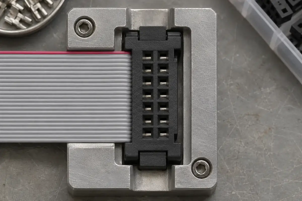
A conductor number describes an electrical assignment, while pitch describes geometry. The first physical conductor does not become the correct circuit simply because it is nearest a latch or a colored body feature. Connector drawings may number contacts as seen from a specified face. The cable drawing and the assembly instruction need a consistent viewpoint to connect that numbering to the wire path.
For a two-row connector, write down the mapping instead of assuming that one complete row corresponds to the first half of the cable. Alternating arrangements are common, but the actual contact design governs. A quick sketch with the viewing direction can expose an accidental mirror image before a mold, fixture or test adapter is built around the wrong interpretation.
Polarization helps control mating orientation after assembly. It does not necessarily stop a cable from being placed incorrectly during termination. A centered external key and a conductor-one marker serve different functions. Our pin-one orientation article follows those separate controls from cable preparation through final circuit verification.
Electrical continuity testing can confirm a specified mapping, provided the test adapter and expected net list are correct. A simple check that each end has some continuity is insufficient for a cable with crossed or mirrored assignments. Preserve the intended pin map as controlled information so that the assembly fixture and electrical tester are not independently interpreting the same ambiguous drawing.
Turn the mapping into useful molding requirements
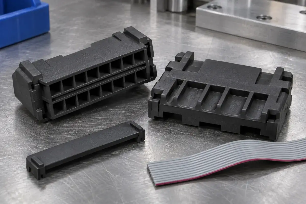
Once the interfaces are understood, identify which molded features locate contacts, which guide the cable and which simply provide clearance. Give the mold designer the relationship between them. This prevents a change to an external wall or a cosmetic centerline from unintentionally shifting the cable path while all individual dimensions still appear plausible.
Sample review should use the selected contacts and cable, assembled with the intended tooling. Inspect the cable location before and after closure, then verify the specified circuit mapping. Where a mismatch appears, separate cable variation, contact position, molding variation and fixture location. Changing all four at once makes it difficult to identify why a subsequent sample behaved differently.
For custom IDC plastic components, provide a cable cross-section, contact layout and mating-face definition with explicit view directions. State whether the requested supply is an empty molded housing or an assembled connector. Those inputs let the quotation and sample plan focus on the actual interface instead of relying on a single pitch label.