
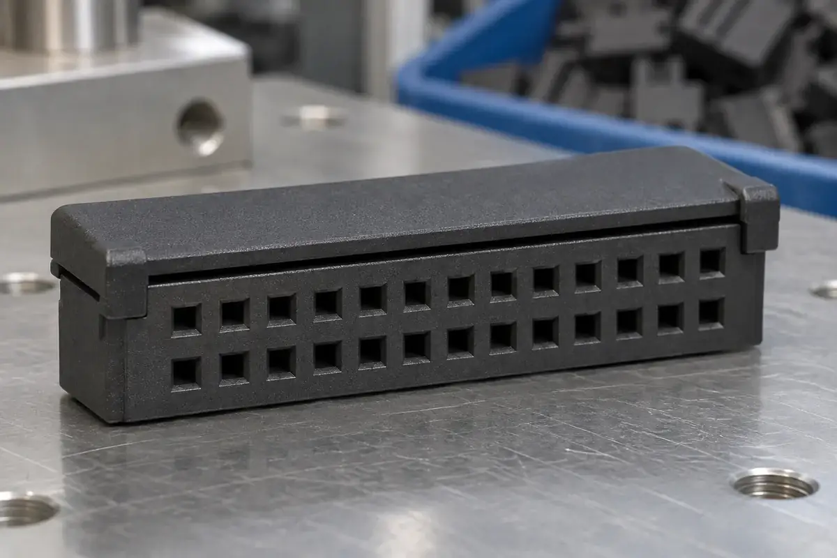
A preassembled IDC connector reaches the assembly station with its cover already associated with the housing. That can reduce loose-part handling, but the cover still needs to leave the cable-loading path available. The intermediate state is therefore a functional condition of the product, not simply an unfinished version of the final latch position.
For a custom molded cover, define what must be retained, what must remain free and what initiates the next movement. The part needs enough stability for its intended packaging and handling while allowing the selected cable to reach the correct position. If those requirements are left implicit, a design can become easy to ship but difficult to load, or easy to load but unreliable to handle.
Product design illustrations accompany the assembly and manufacturing explanations below.
Describe the preassembled state explicitly
Start with a section showing the housing, contacts and cover before cable insertion. Identify the surfaces that locate the cover laterally and the features that prevent it separating during normal handling. Then identify the gap or access route used to introduce the cable. A single overall height does not necessarily describe all of these relationships.
The 3M 891 Series description identifies features intended to prevent premature latch locking during shipment. That is a specific design response to a real intermediate-state problem. A custom assembly needs its own defined handling condition rather than assuming that every two-stage-looking latch performs the same function.
Do not equate temporary retention with final engagement. A cover may be intentionally held above its termination position with only part of its guiding or latching system engaged. The inspection method should distinguish the permitted starting state from damage, incomplete preassembly or accidental final closure. Otherwise, an operator may try to correct a good intermediate part into an unusable condition.
The loose state also needs a clear orientation. If the cover can be preassembled in more than one direction, determine whether all of those arrangements are intended. Guides and asymmetric features can help, but their function should be verified against the actual wrong configuration. Visual similarity between the two ends should not be the only assembly instruction.
Balance handling retention with cable access
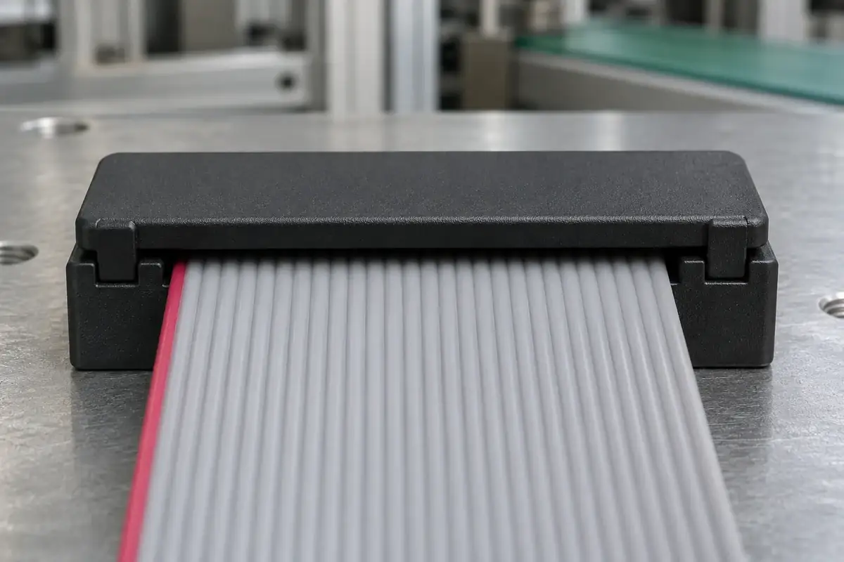
The cover should remain associated with the housing through the agreed handling sequence. Consider removal from packaging, transfer into a nest and presentation to the termination tool. These movements can load the cover in directions that differ from the final press stroke. A latch that is stable under vertical compression may still be vulnerable to an incidental sideways snag.
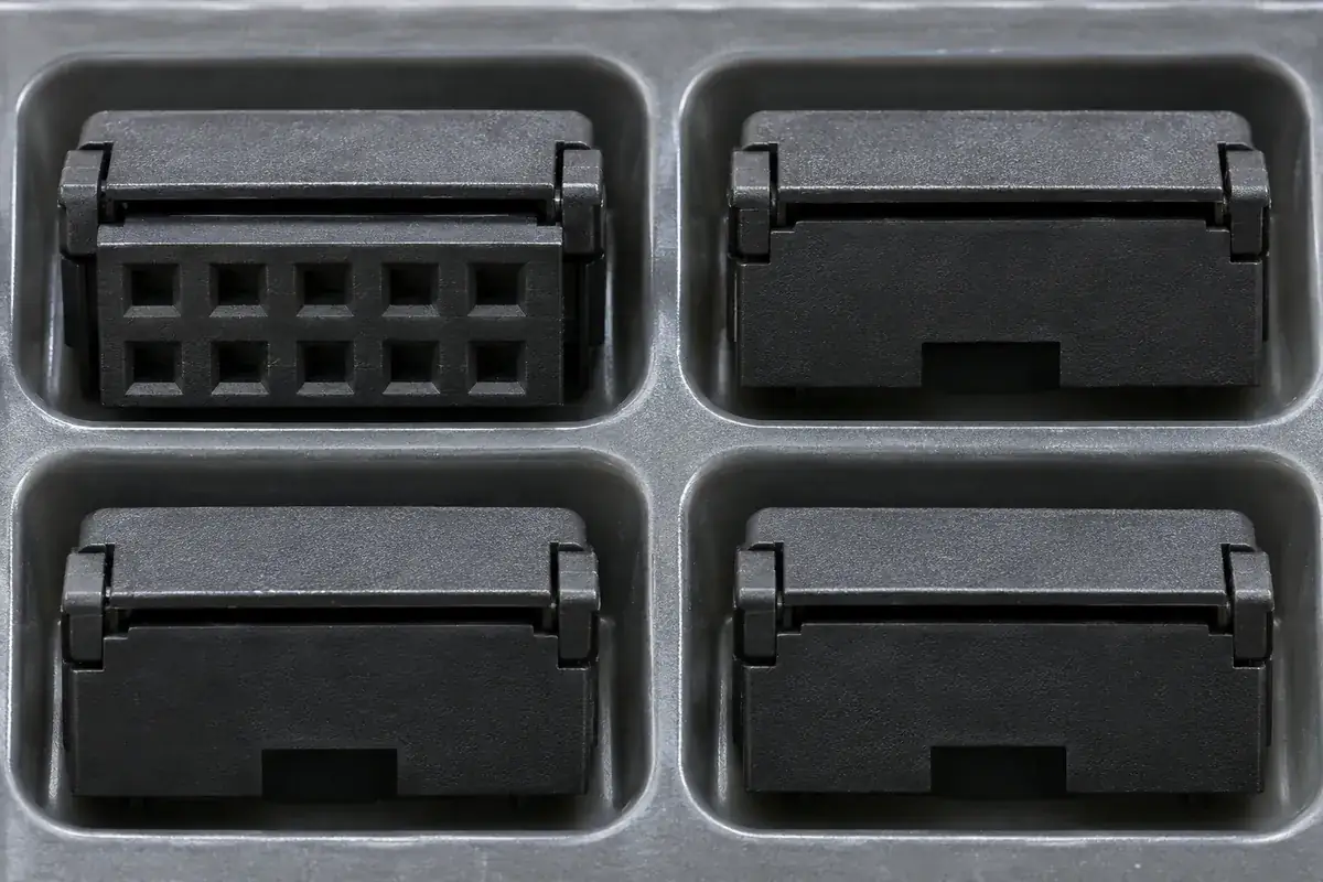
Packaging can support the intermediate state. A tray or carrier may protect projecting cover features and prevent stacking loads from closing the assembly prematurely. Include that support in the supply definition if the design relies on it. Do not test a carefully supported packaging arrangement and then ship the same parts loose without reviewing the changed handling condition.
Cable access needs to be checked with the actual prepared cable, including its edge condition and the length that must pass through the opening. A generous-looking gap can still be obstructed by contact tips or a cover rib. Review the loading direction and available grip space, especially when another connector has already been installed at the opposite cable end.
Our IDC cable-path comparison explains why end and intermediate connections can require different loading sequences. A preassembled cover that works well for a short cable end may be unsuitable for a later station on an already populated ribbon. Resolve the process sequence before finalizing the molded access features.
Control the transition to final termination
The next movement should be defined by the selected assembly process. If a family specifies a preliminary cable-clamping position, distinguish it from final termination; if it specifies one tool stroke, preserve that sequence. The TE AMPMODU 50/50 quick reference guide identifies a cover-closing kit and its associated instruction sheets. Use the applicable assembly instructions to establish the progression of cover positions rather than transferring a sequence from another family.
Guide surfaces should maintain the intended cover relationship as the temporary retention is overcome. If one end releases first and the other remains caught, the cover can rotate into the cable. Review the transition region rather than only the two end positions. A design can look correct when fully open and fully closed while moving through an unsuitable path between them.
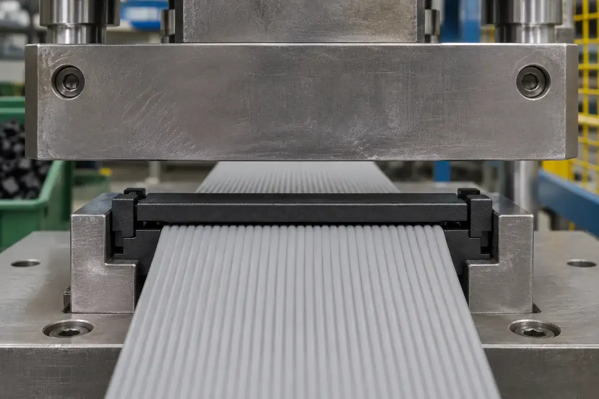
The press nest and platen need to support that transition. Their contact surfaces should apply the intended closing movement without catching a temporary-retention feature or loading a thin edge. Tool access and molded geometry should be reviewed together. Adding an intermediate detent after the tooling has been designed can change the force path and require a new assembly evaluation.
Keep rework assumptions explicit. If a cover reaches the final latch position before cable loading, reopening it may not be permitted or may require a defined procedure. Do not treat repeated opening as harmless simply because the plastic can flex. The intermediate retention and final latch can have different intended life or inspection requirements.
Inspect both the received state and the finished assembly
Incoming or in-process inspection should verify that the cable-loading state is usable. Check the defined cover position, retained orientation and relevant damage limits. These checks are different from the final termination-height and latch checks. Keeping them separate helps identify whether a problem originated during molding, preassembly, packaging or the later termination operation.
Where samples are used to evaluate handling, record the packaging and transfer sequence. A part carried directly from a bench to the press does not demonstrate the same condition as one transported through the intended production flow. Avoid turning an informal handling observation into an unqualified shipping-performance claim; define the actual evaluation and its acceptance criteria.
For custom preassembled IDC covers and housings, provide drawings for the intermediate and final states, along with the cable-loading route and tooling approach. The related uneven closure guide can help when the transition introduces tilt. A clear definition of both states makes the molded features easier to manufacture and inspect consistently.