
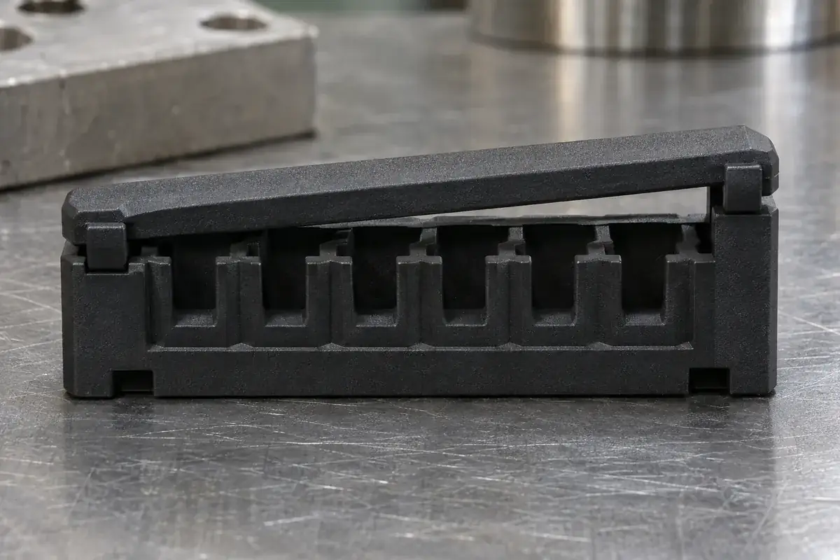
When an IDC cover catches on one side before the other, it is tempting to press harder on the open end. That may make the part look closed while hiding the reason it became tilted. Cable position, cover orientation, fixture support and molded latch geometry can all contribute. The useful first step is to preserve the assembly state long enough to understand which feature contacted first.
Uneven closure matters because a ribbon-cable connector terminates multiple conductors through one coordinated movement. A cover that rotates while closing can load the cable and contact array differently across its width. The visible latch is therefore one clue in a wider termination problem, rather than a reliable indicator that the other positions are already acceptable.
Product design illustrations accompany the assembly and manufacturing explanations below.
Separate the initial cable position from the final latch event
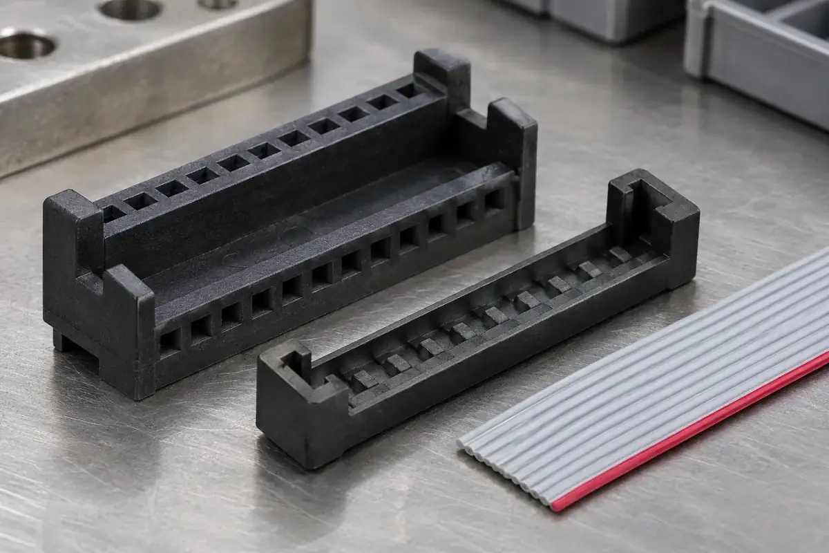
Inspect the cable before pressing. A ribbon seated over a guide wall, a folded edge or an incorrectly routed end can lift one side of the cover. The cable may look centered from above while sitting at different heights underneath. A side view or controlled section of the loading arrangement often explains a tilt that is difficult to see through the top opening.
Confirm that the cover is presented in its intended orientation. Similar-looking ends can carry different guiding or latch features. A part that can be placed over the housing is not necessarily aligned for its full travel. Compare the actual component revision with the assembly drawing, particularly if tooling or packaging has changed since the last accepted sample.
Check whether the assembly uses a defined preclosed state. Some designs retain the cover loosely before the final termination operation, while others begin with separate components. The starting gap and permitted cable-loading direction depend on that construction. Our preassembled-cover article explains why an intermediate detent should not be confused with the finished latch condition.
A cable that is slightly skewed can create a progression of contact instead of uniform engagement. Do not correct that by dragging the cable sideways after contacts have begun entering the insulation. Follow the selected connector's handling and rework limits. Preserve the suspect assembly for review when moving it would destroy the evidence of the original cable position.
Review the press and nest as part of the system
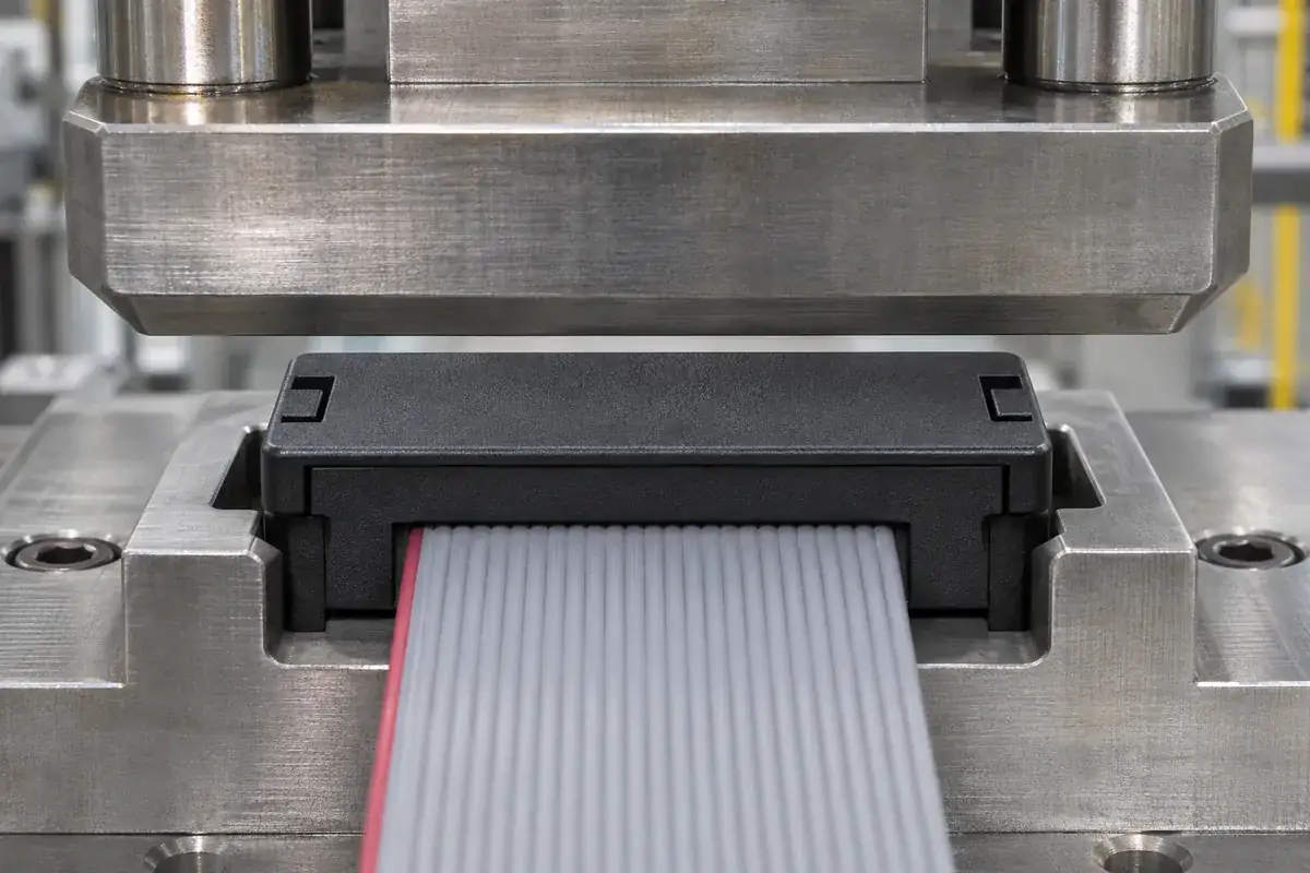
A flat-looking platen does not guarantee balanced loading if it contacts only a raised rib or one end of the cover. The approved tool must load the intended surfaces over the required travel. A substitute tool can introduce rotation even when the molded components are dimensionally correct. Examine witness marks and the actual contact pattern rather than judging the tool from its overall shape.
The lower nest is equally important. If the housing rocks on a gate vestige, an incorrect ledge or an obstruction beneath one end, the upper platen can be parallel to the machine while the connector is not. Define which housing surfaces establish the assembly plane. Clearance pockets should allow non-datum features to remain clear throughout the operation.
TE's AMPMODU 50/50 quick reference guide identifies dedicated cover-closing equipment and its instruction sheets. The practical lesson is to treat tooling as part of the selected assembly process. It does not provide a universal press setting or authorize the same nest and platen for unrelated IDC designs.
Machine alignment should be evaluated under the relevant operating conditions. A long cover may respond differently from a short one, and a worn guide can allow lateral motion before the final stroke. If several connector lengths share equipment, verify the intended support and loading arrangement for each size rather than assuming that a successful short assembly establishes the full range.
Measure latch geometry without losing its assembly context
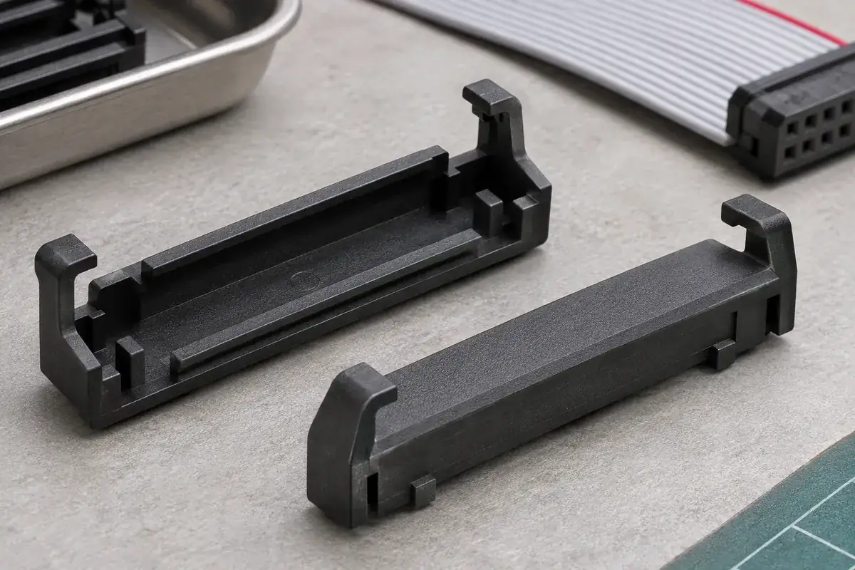
Once cable loading and tooling are understood, compare the molded parts. Relevant features may include cover flatness, latch-arm position, catch height and the relationship between guide rails and the housing seat. An isolated latch dimension can be acceptable while its position relative to the opposite end is not. Measure from references that correspond to the way the parts meet.
Flash, damaged edges or ejection distortion can change the first point of contact. A small obstruction in a guiding region may force the cover to rotate before either latch reaches its intended engagement. The solution may be controlling that local feature rather than making the latch more flexible. Record the defect location so the molding team can relate it to parting, shutoff or handling conditions.
Resin and conditioning should remain consistent with the approved part definition. A change in stiffness can alter how a cover responds to an uneven load, but that does not mean flexibility should be used to compensate for poor alignment. Review the material and geometry together with the actual assembly conditions. A part that bends around an obstruction may still leave an incorrect termination.
Compare empty component fit with the loaded assembly only where the procedure permits it. The difference can help identify whether interference begins at the plastic interface or after the cable enters the load path. Do not repeatedly cycle production samples merely to make the fit easier; latch behavior after repeated manipulation may no longer represent the intended first assembly.
Confirm termination after correcting the cause
A balanced-looking cover is an improvement in appearance, not the entire acceptance decision. Check the specified finished dimensions, cable position and electrical condition after the process change. The final termination-height discussion explains why a latch click and a height measurement answer related but different questions.
Change one identified contributor at a time where practical. Record the component revisions, cable lot, tooling setup and inspection method so the result can be reproduced. If several changes are necessary together, document that limitation rather than attributing the improvement to whichever dimension was easiest to measure. The objective is a controlled assembly process, not an unexplained successful sample.
For custom IDC cover and housing development, include the termination tool arrangement and the observed uneven state in the review package. Photographs from both ends, alongside the controlled drawings, can make the sequence easier to understand. Keep actual measurement and test results separate from these product design illustrations when approving the final assembly.