
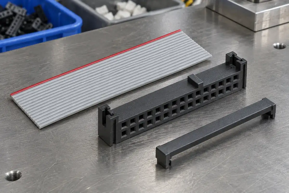
The red edge of a ribbon cable is a useful visual reference, but it cannot independently define the electrical pinout of a finished assembly. Someone still has to connect that edge to a conductor assignment, a connector view and the intended contact position. An IDC cover can close neatly around a cable that has been turned over or approached from the wrong direction.
For a new assembly, treat orientation as a sequence of decisions rather than a single mark. Establish the cable reference, the connector reference and the viewpoint used in the work instruction. Then check how those references remain visible while the cable is loaded, the cover is closed and the completed assembly is tested.
Product design illustrations accompany the assembly and manufacturing explanations below.
Start with the cable identification convention
A colored edge commonly identifies one side of a flat ribbon cable. The cable specification should state what that identification means for the assembly being produced. Do not rely on an operator remembering that a stripe always belongs on a particular side of a bench fixture. That relationship changes when a fixture is mirrored, a cable is flipped or the connector is approached from another end.
The conductor assignment should be visible on a controlled cable or harness drawing. Include the viewing direction and connector orientation, especially when the cable terminates at different connector types. A photograph can explain the routing, but the electrical definition must remain clear if the photograph is printed in grayscale or the housing color changes between otherwise approved variants.
Color is also an imperfect sole control because lighting, contamination and cable preparation can obscure it. A cover or strain-relief bar may hide the edge once installed. Decide where orientation is checked while the reference is still visible. A later inspection should not depend on seeing a stripe that the approved assembly process deliberately conceals.
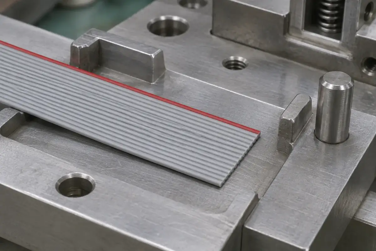
If cable cutting or separation is part of the process, retain traceability to the original edge. A short loose section can be easy to reverse after it leaves the cutting fixture. Arrange the next operation so the cable enters in a defined state. This is a process-design question as well as a molded-feature question; a better mark cannot solve every handling ambiguity.
Identify the connector reference and viewing face
The connector drawing should define position one from a stated view. A mating-face view and a cable-entry view may appear reversed when placed beside each other. That reversal is a drawing perspective issue, not necessarily an electrical crossover. Label the views explicitly and follow a single contact through the section if the relationship is not immediately clear.
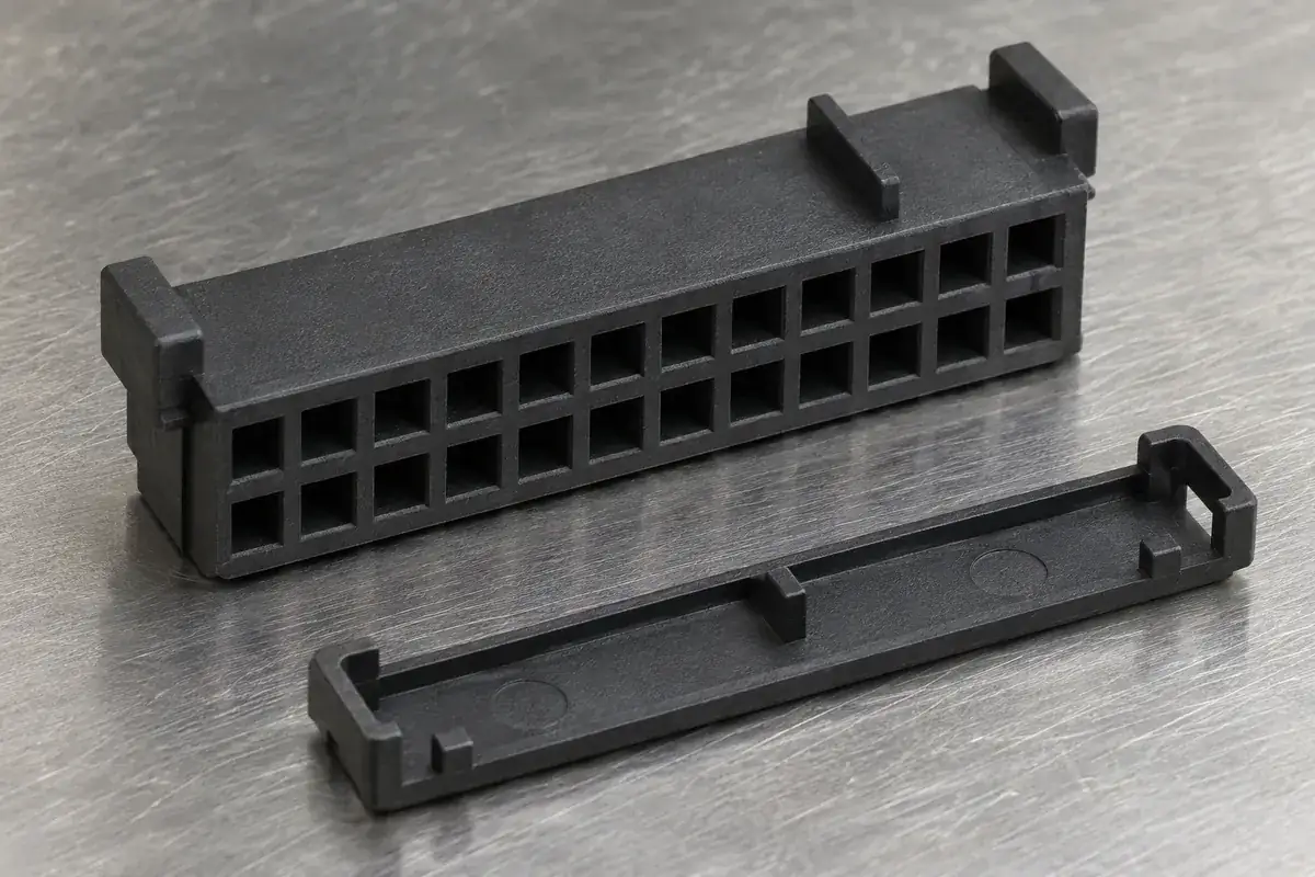
The 3M 891 Series drawing identifies an orientation triangle. Use the current drawing for the selected part to interpret its markings. A custom housing can use another reference scheme, so a triangle, notch or raised feature should have a defined meaning rather than being copied as a decorative detail.
For injection molding, consider the mark's location and visibility in the real assembly. A small recess near an edge may be difficult to distinguish from a gate vestige or ejector witness. Place the feature where the operator or inspection camera can see it without rotating the cable into an unapproved position. Visibility after molding and visibility during assembly are different checks.
Marks also need a revision strategy. If one external housing serves several electrical configurations, a permanent molded symbol should describe a stable mechanical reference rather than a circuit assignment that changes with the harness. Variant identification may belong on an assembly label or controlled packaging. The objective is to reduce interpretation, not to put every instruction into the mold.
Understand what the polarization key actually prevents
A key can prevent an incorrectly oriented socket from entering its mating header, provided the selected pair and approach are as specified. That protection acts at the mating interface. It does not automatically control how a flat cable is placed into the rear of the socket before termination. These are different interfaces and should be checked separately in the assembly review.
A fixture can link the two operations by locating the housing from its key or another stable datum while presenting the cable in a defined direction. The fixture still needs to leave the cable edge visible and permit the cover to move correctly. A locating feature that is convenient for the nest but unrelated to the controlled connector orientation can introduce a new ambiguity.
The distinction is similar to the one discussed in connector polarization keys: a feature should be evaluated against the specific wrong assembly it is intended to prevent. A physical key may block one rotation while allowing a cable to be reversed elsewhere. List the plausible mistakes and assign a control to each one.
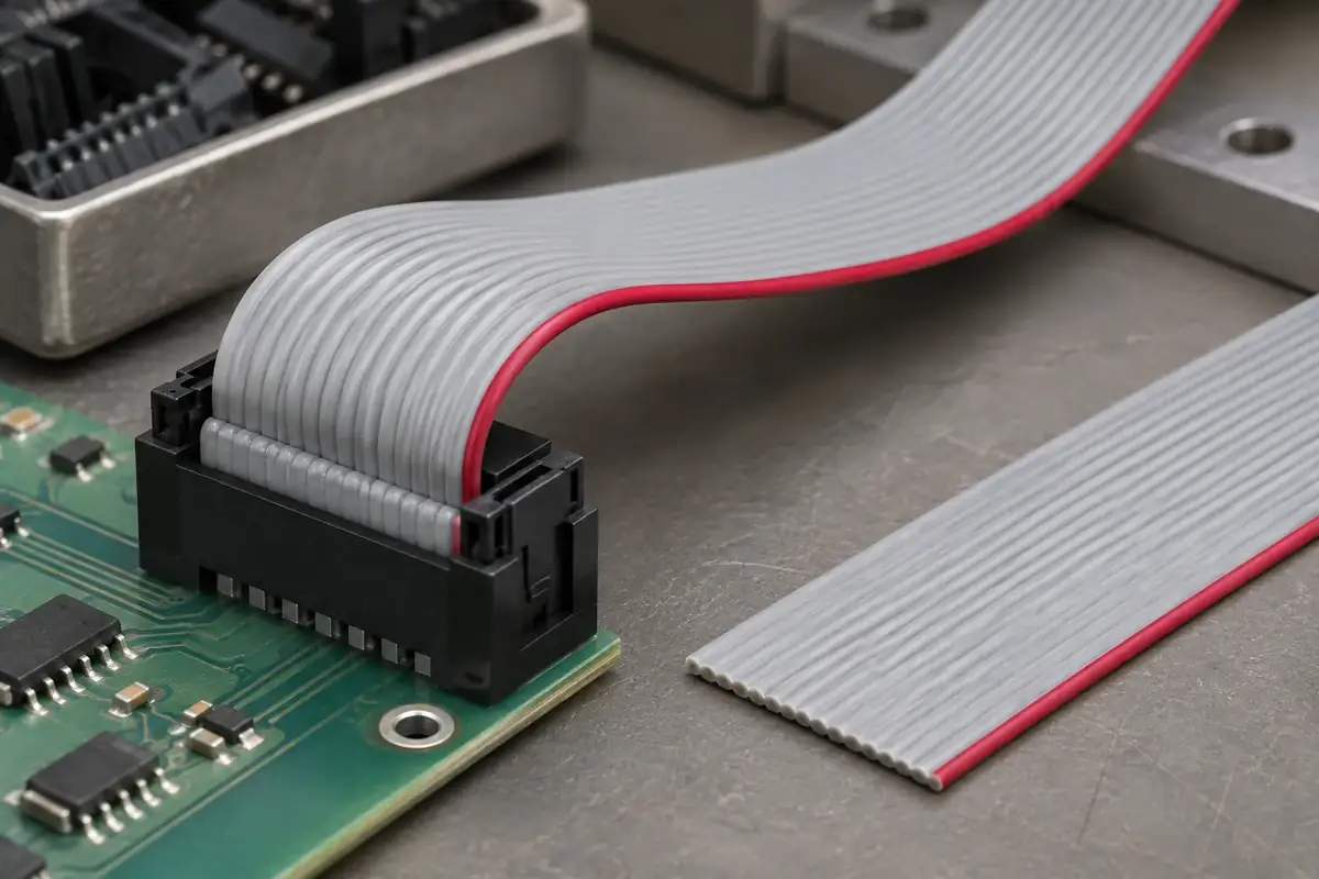
Foldback routing deserves particular attention. After the ribbon turns back across a cover, the red edge may appear on a different side from the initial loading view. The conductor has not changed identity, but the observer's perspective has. Include the fold direction in the assembly depiction so a correctly routed cable is not rejected or an incorrect one accepted because of a misleading final photograph.
Verify the intended circuit rather than the appearance alone
Before releasing the assembly, compare the controlled contact map with the fixture orientation and electrical test definition. A mirrored test adapter can validate a mirrored cable if both were built from the same mistaken interpretation. Independent review of the mating-face references helps prevent that circular confirmation. Preserve enough drawing information for another person to reconstruct the mapping.
The inspection record should distinguish orientation, cover condition and electrical results. A correct stripe location supports one part of the check; it does not establish contact quality or insulation performance. Our IDC assembly verification guide separates those questions so a visible assembly feature is not used as a substitute for the required electrical evaluation.
For custom IDC housings and covers, share the cable identification convention, connector views and loading sequence with the plastic drawing. Include the intended fixture and any camera view. The molding review can then place useful references and keep them visible at the point where they actually prevent an orientation error.