
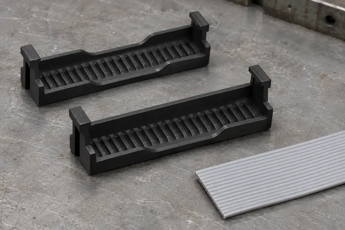
An IDC connector placed at the end of a ribbon cable has a different routing problem from one installed partway along the cable. In the first arrangement, the cable can terminate within a defined end region. In the second, it must continue beyond the connection. The cover, housing and tooling must accommodate the intended route together; an opening in one plastic part is not sufficient by itself.
Terms such as open-ended and closed-ended are useful only when the relevant opening is identified. They may refer to cable access, an end stop or another feature in a particular connector family. Start with a section showing where the cable enters and exits. That makes it possible to discuss an intermediate connection without confusing it with a different mating-face construction.
Product design illustrations accompany the assembly and manufacturing explanations below.
Define whether the cable ends or passes through
An end connection needs a controlled relationship between the cable end and the termination region. A stop can help establish that position, but it must correspond to the approved cable preparation and contact geometry. A stop placed for convenient molding can leave the conductors too far into the connector or too close to an exposed edge. Review the actual contact section before assigning the stop location.
A pass-through connection needs a clear path on both sides of the termination. The cable should remain flat and located while the cover closes. An exit recess in the cover can be useful, but the housing beneath it, the press nest and any later restraint also need clearance. Check the entire assembled path rather than approving the cover as an isolated part.
The 3M 891 Series information describes a cover recessed for cable termination from either side. That statement concerns the specified product construction. It should not be expanded into a claim that any connector with a similar recess supports every intermediate connection or cable-routing arrangement.
For an intermediate location, identify the connection's electrical purpose and the permitted cable construction. The contact system and application requirements determine whether the proposed arrangement is acceptable. A molded pass-through path solves a mechanical routing question; it does not by itself establish circuit behavior, signal integrity or the suitability of an added branch.
Consider how the cable reaches the assembly station
A short cable end can often be presented directly to the connector. A mid-cable location may require handling two long free sections while keeping a marked station aligned with the contact pattern. The fixture should support those sections so their weight or twist does not pull the cable out of position. This is especially relevant when the connector is small compared with the attached cable length.
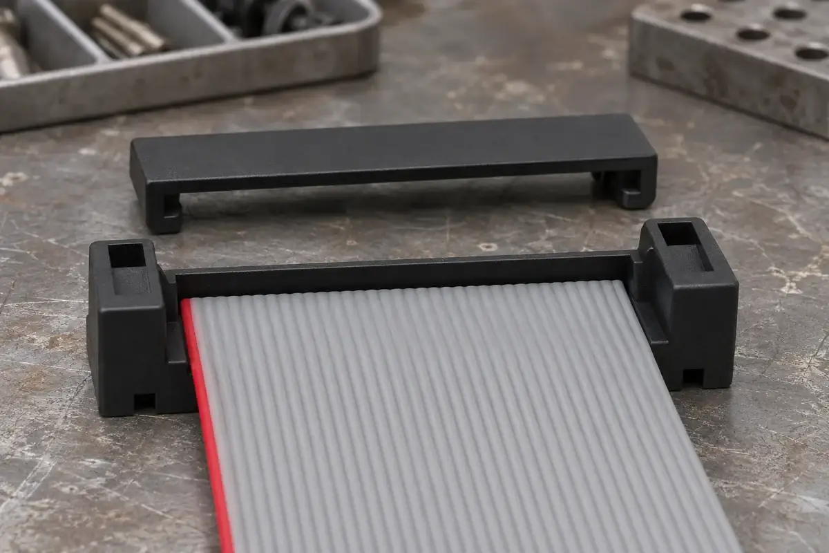
Preassembled covers can simplify component handling, but their loading path must allow the intended cable position to be reached. A design that requires threading the entire cable through a small opening may be impractical after another connector has already been installed. Review the build sequence, including which terminations are completed first and what remains accessible afterward.
A side-loading or separate-cover arrangement can offer access at an intermediate station, but it can also require more deliberate cable location before pressing. The choice should be based on the selected connector system and assembly process. Do not remove a housing wall simply to create access without checking what that wall previously located, supported or insulated.
The preassembled-cover guide follows the distinction between component retention and final closure. For a branch or pass-through arrangement, add the cable-loading route to that review. A stable loose cover is useful only if the real cable can be positioned without damaging contacts, overstressing latches or disturbing earlier terminations.
Keep cable exit clearance distinct from restraint
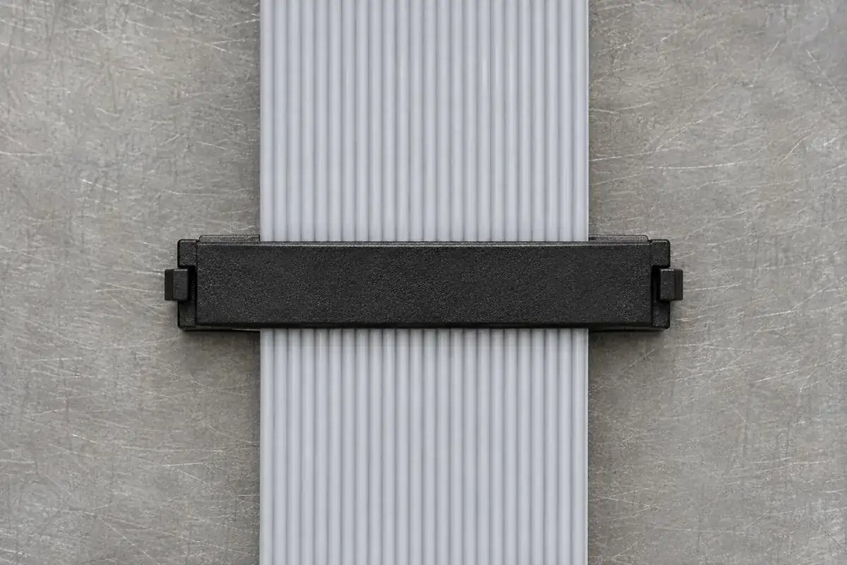
An open exit permits the cable to continue; it does not necessarily restrain movement. If a free cable section can pull directly on the termination, the assembly may need a defined support arrangement elsewhere. Identify where loads from each side are reacted. A restraint intended for an end-foldback configuration may not suit a straight pass-through route.
Conversely, a closed end can locate the cable without providing strain relief. Its wall may be intended as a positioning reference rather than a load-bearing stop for repeated cable tension. Specify the functional role so the molded feature is not assigned a duty that was never evaluated. The electrical joint should not become the unintended structural anchor for external handling.
Cable edge and end condition also affect the local geometry. A rough cut, twisted ribbon or excess end length can contact a cover wall during closure. Define the preparation and inspection requirements that support the selected arrangement. Increasing cavity length may hide an inconsistent cutting process while changing the cable's relationship to the contact region.
Our foldback and strain-relief article explains how to follow the load path beyond the termination. Apply that reasoning to each cable exit independently. Where two free sections leave an intermediate connection, their installed directions and supports can differ even though they share one connector body.
Release the actual arrangement rather than a cover label
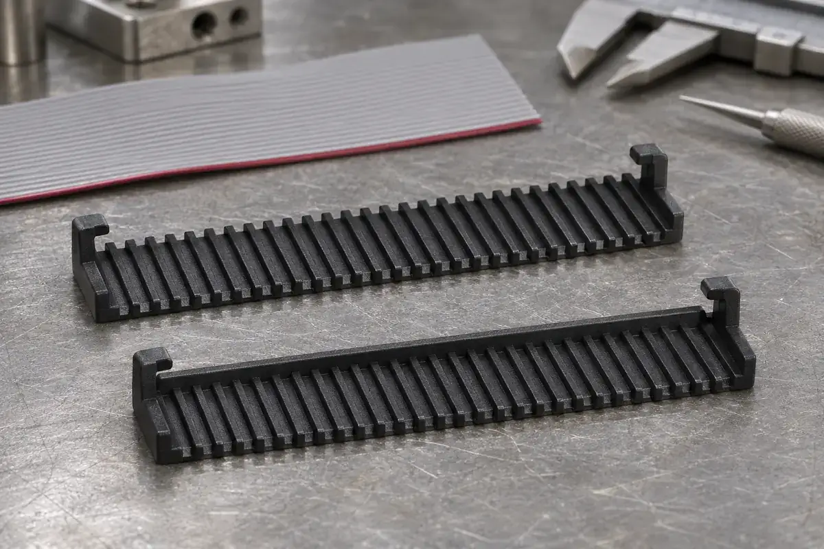
The drawing package should show the cable station, entry and exit direction, contact orientation and surrounding access. Include the complete assembly sequence when multiple connectors share one ribbon. This helps identify a routing problem before it is transferred into the mold design or discovered only after the first connector has made the next operation inaccessible.
Sample evaluation should reproduce the intended cable length and handling where those conditions affect loading. A small loose cable coupon may be useful for initial fit checks but cannot demonstrate every feature of a long pass-through assembly. Keep those stages distinct, and use the required electrical and mechanical checks to approve the final configuration.
For custom IDC cover and housing components, send a section through the cable path with the molding drawings. Explain whether the cable ends, continues or folds at the connector. A precise assembly description gives the quotation and tooling review more useful information than the words open-ended or closed-ended alone.