
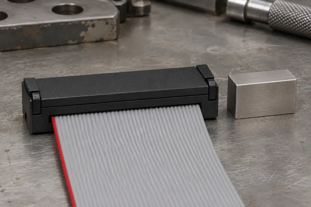
An IDC cover can appear fully latched while the assembly still needs a dimensional and electrical check. The latch retains the cover; the termination process places conductors into the selected contacts. Those functions interact, but one visible feature does not measure all the others. A useful finished-height requirement therefore starts with a clearly defined assembly state and reference surfaces.
For a custom housing and cover, avoid specifying only an overall dimension taken from whichever surfaces are easiest to reach. Decide what the measurement is intended to reveal. It may help confirm cover position after termination, detect an uneven assembly or control packaging clearance. Different purposes can require different references and should not be merged into one ambiguous number.
Product design illustrations accompany the assembly and manufacturing explanations below.
Define what is included in the measured assembly
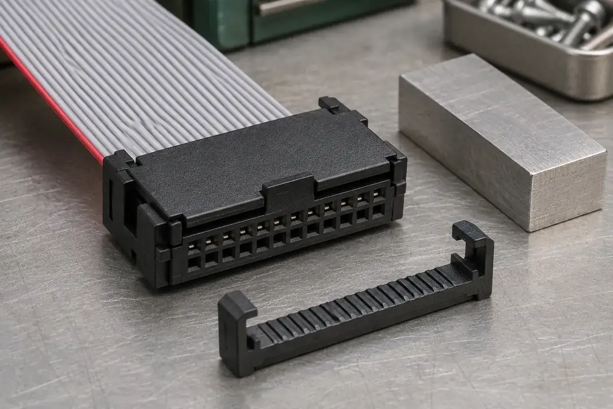
A connector with a separate strain-relief bar can have more than one relevant height. The housing-and-cover height describes one assembly state; the height after fitting the restraint describes another. A cable folded over the cover may also affect the accessible surfaces. State which components are installed and whether the cable is in its final route when the measurement is taken.
Use the selected connector's drawing and application instructions to establish the reference. Do not transfer a dimension from a similar family because the position count or external width matches. Contact design, cable accommodation and cover construction can differ beneath a familiar shape. A copied height may close the plastic while placing an unsuitable load on the actual conductor-contact interface.
The TE AMP MONO-SHAPE application specification separately addresses finished housing-and-cover height and wire inspection. This is a different connector system, so its numerical limits do not apply to a ribbon socket. It illustrates the distinction between an assembly dimension and evidence about the terminated conductors.
Define the measuring force and method when flexible features or cable material can influence the reading. A gauge that compresses the assembly can make a high part appear acceptable, while a contact point on a flexible latch can give an unstable result. Choose repeatable surfaces connected to the intended cover position, and record the method with the dimensional requirement.
Distinguish tool travel from the released part height
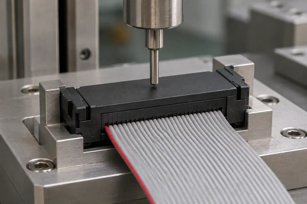
The press stroke is a process setting, while the released assembly height is a condition of the part. Tool compliance, nest support and the response of the components can separate those two values. A machine reaching its programmed position does not alone establish that the connector reached the intended state. Confirm the part condition using the specified inspection method.
Support references should remain consistent between assembly and measurement. If the press nest locates the housing on one ledge while the inspection fixture rests it on a different protrusion, the two operations may be evaluating different relationships. Review the datum chain from the lower housing surface through the contact region to the cover pressure face.
Measure at enough locations to distinguish overall position from tilt where the drawing requires it. A single reading near one closed latch can miss a high opposite end. That does not mean every connector needs an arbitrary multi-point inspection plan; it means the plan should detect the relevant failure mode. Our article on one-sided cover closure follows the causes of that uneven state.
Part geometry can also make an overall height misleading. A raised identification feature, local molding witness or decorative rib may sit above the functional pressure face. Decide whether it belongs in the measurement envelope or should be cleared by the gauge. The molded drawing and the inspection drawing should describe the same intent rather than leaving each operator to choose a contact point.
A closed latch does not reveal every conductor condition
A latch can engage after the cover reaches a certain position, but the relationship between that position and conductor termination depends on the selected construction. Cable thickness, conductor geometry and contact location remain part of the system. The same visible latch state can therefore coexist with a cable that is skewed, incorrectly oriented or outside the approved accommodation range.
Electrical checks need their own acceptance criteria. Continuity confirms the intended connection only when the mapping and test method are appropriate; it does not automatically establish every aspect of connection quality. Insulation, contact resistance or other evaluations may be required for the application. Select them from the approved specification rather than treating a dimensional result as a substitute.
Where destructive examination is required, define how samples are selected and prepared. A section through a termination can help explain conductor position, but preparation can also disturb the feature being examined. Use an agreed method and preserve the association with the cable, contact and tooling revisions. Do not generalize one convenient section into an unqualified statement about every position or batch.
The IDC verification guide separates mechanical closure, cable placement and electrical evaluation. Keeping those records distinct makes a problem easier to diagnose. If the cover height passes but the electrical result does not, the team can investigate the remaining interfaces instead of repeatedly adjusting a dimension that is already within its intended range.
Make height control useful during development and production
During sampling, compare measured heights with the actual assembly observations and required tests. Record whether the part was measured immediately after termination or after an agreed conditioning period. If the inspection state changes, preserve that distinction. A nominal number without its component configuration, references and method is difficult to reproduce or use for a tooling correction.
When investigating a drift, examine the cable and contact definition, tool condition, housing support and molded dimensions in a structured order. An apparent height change may originate in the fixture rather than in the mold. Conversely, a stable machine setting can conceal a shifted molded reference. Retain enough process information to separate these possibilities before changing the production setup.
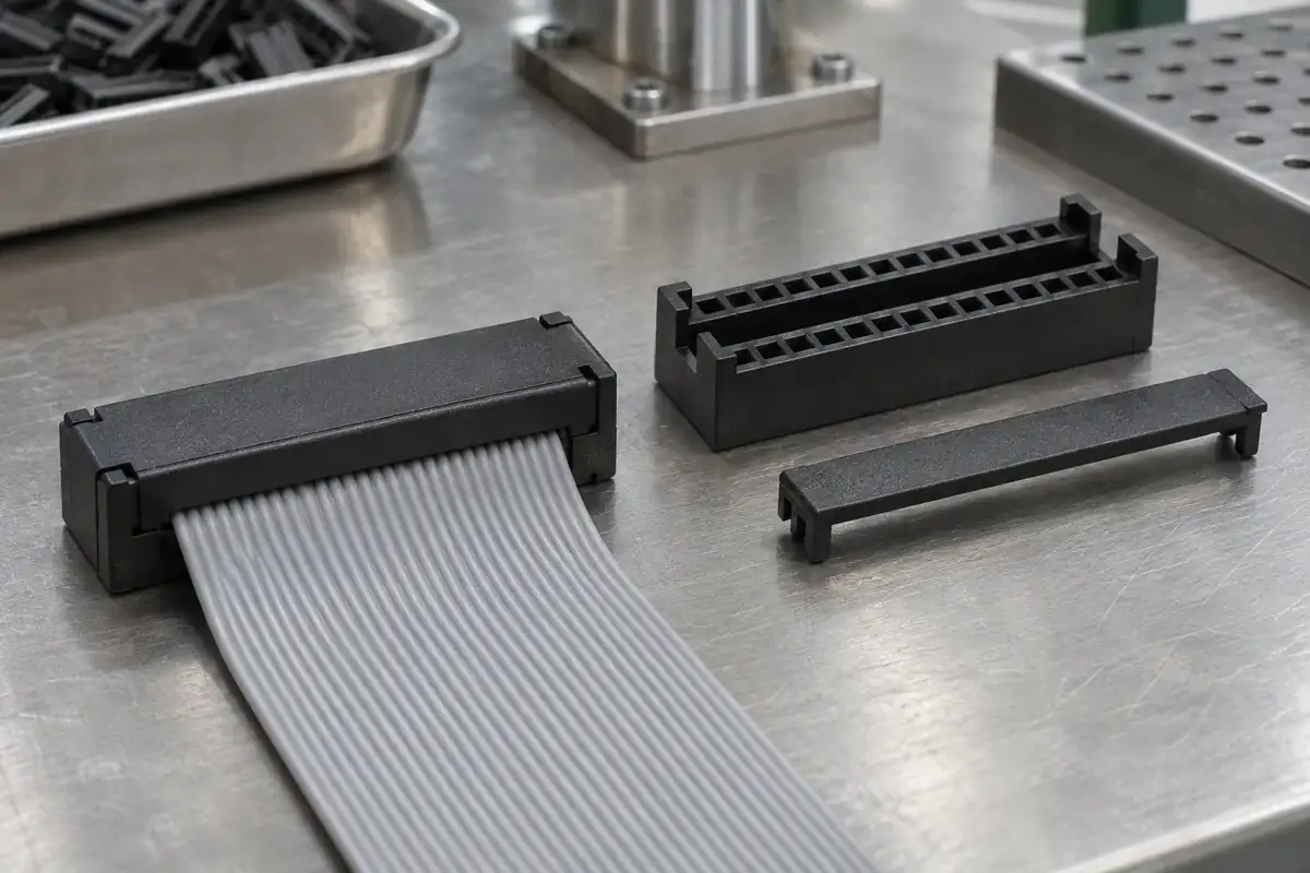
For custom IDC housings and covers, include the intended finished-height references and assembly state in the quotation package. Share the cable and contact drawings as well as the plastic model. This allows the molding, fixture and inspection reviews to work toward the same finished condition instead of using latch closure as a shorthand for complete acceptance.