
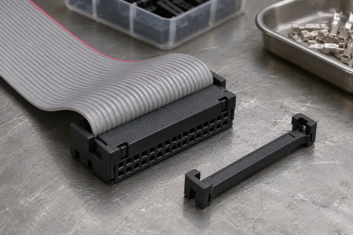
A ribbon cable can be electrically terminated and still need a separate way to manage handling loads. Pulling or bending the free cable close to the connector can disturb the region where the conductors meet the IDC contacts. A foldback and strain-relief bar changes that load path, but its effectiveness depends on the selected connector construction and the way the cable is routed.
The useful review begins outside the plastic part. Follow the free cable from its next support toward the connector, then identify where tension and bending are reacted. This reveals whether the restraint supports the cable as intended or simply creates another sharp bend immediately beside the termination. A visible bar alone does not establish an acceptable cable assembly.
Product design illustrations accompany the assembly and manufacturing explanations below.
Separate the termination cover from the restraint
The termination cover establishes a controlled relationship between cable and contacts during the assembly process. A separate strain-relief component may then hold a folded cable against the connector or cover. Those parts can use nearby latch features while performing different jobs. Identify which component is responsible for termination and which is intended to react subsequent cable handling loads.
The 3M 891 Series strain-relief accessory is identified separately from the socket. That distinction is useful when defining a custom supply scope. The selected connector's documentation determines the compatible accessory and assembly route; a bar with a matching width is not enough to establish that compatibility.
A restraint may press on the cable insulation over a defined region. The supporting plastic beneath it must carry that load without concentrating it at an unintended edge. Review the contact area, closure state and cable thickness together. A clamp that seems secure because it strongly deforms the ribbon may be outside the intended cable accommodation.
The cover and restraint also affect the finished assembly envelope. The cable may rise above the cover before turning back, and the restraint can increase the total height. Keep these dimensions separate from the termination-height requirement. Our IDC height article explains why the measured component state needs to be specified.
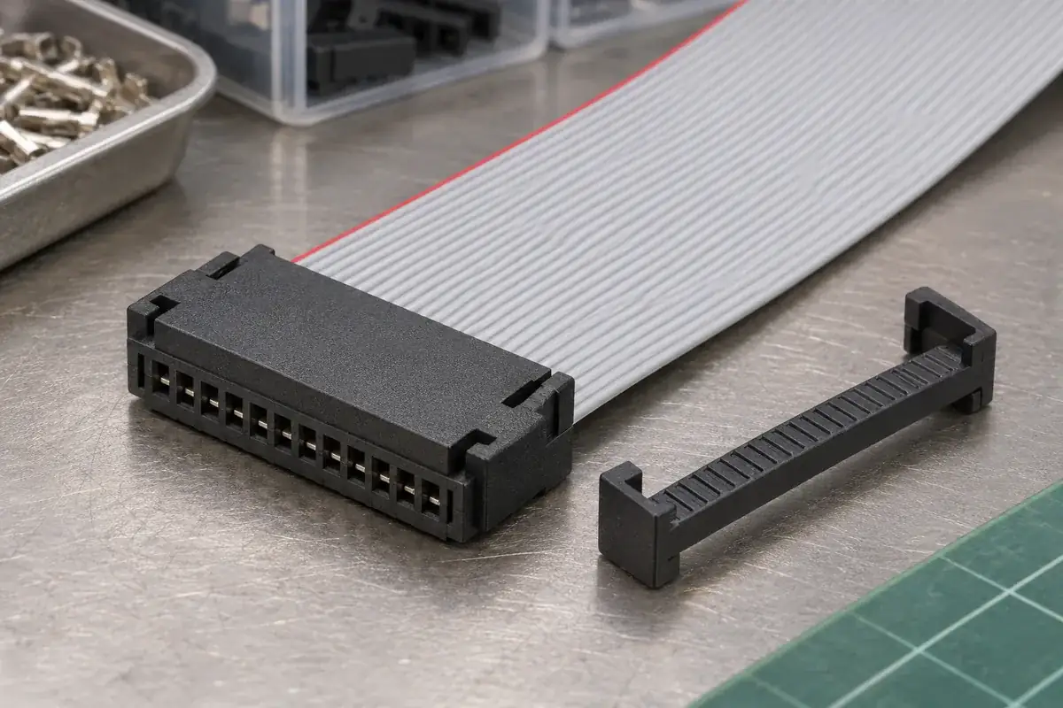
Give the fold enough space to follow the approved route
The cable's permissible bend depends on its construction and application. Use the cable and connector requirements instead of inventing a universal fold radius. A thin-looking ribbon can still contain conductors or insulation that should not be sharply creased. The assembled drawing should show the route that the qualification or application review actually evaluates.
A foldback can change which side of the ribbon appears visible from a given viewpoint. This matters when the colored edge is used during assembly inspection. Preserve the conductor-one definition through the bend and label the viewing direction in the work instruction. The apparent side of a stripe after folding should not replace a controlled circuit map.
Space around the connector matters as much as the bar geometry. An enclosure wall, adjacent board or cable tie can force the ribbon into a tighter bend than the assembly drawing shows. Review the installed route and service access, including the position of the first external support. A restraint cannot isolate the termination from every load if the surrounding layout continuously forces the cable against it.
Where the cable is expected to move during use, define that movement explicitly. An assembly intended for occasional installation handling is not automatically suitable for repeated flexing. The required evaluation belongs to the complete cable and connector arrangement. Avoid assigning a flex-life claim to a molded restraint based only on its material or external appearance.
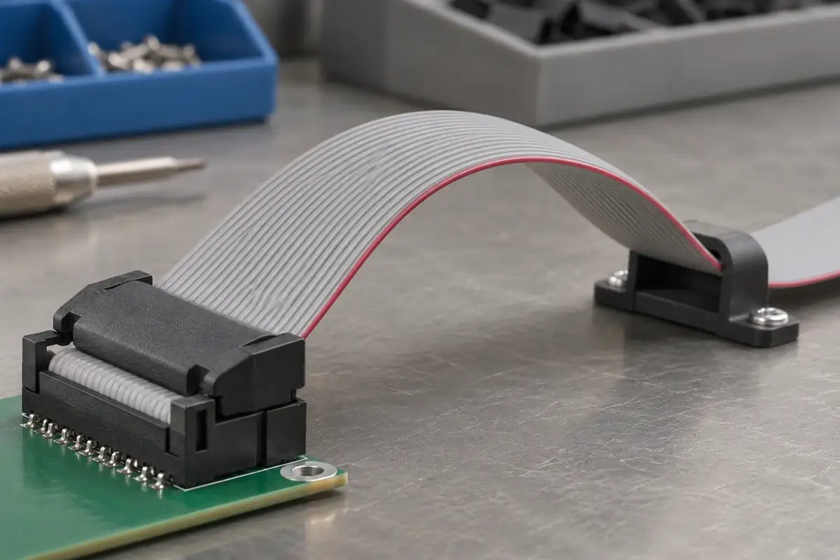
Trace force through the restraint and its latches
When the free cable is pulled, the load should enter the intended support surfaces and then pass through the restraint attachment into the connector structure. Examine how the latches react that load. A latch that mainly retains the bar during handling may behave differently from a feature intended to sustain a defined service load. Specify the required function before altering the latch thickness.
The molded bar can bend between its attachments. That changes the pressure distribution on the cable and can lift part of the restraint away from its support. Wall section, local ribs and material stiffness influence this behavior, but the solution should follow the actual load path. Adding a tall central rib may interfere with enclosure clearance without improving the attachment region that governs the problem.
Gate vestige, flash or rough edges near the cable path deserve specific limits. A small molding feature can become a rubbing point when the cable moves. Identify contact surfaces on the drawing and review them after molding and assembly. Cosmetic acceptance alone may miss a feature that matters to the cable insulation but is hidden after the bar is installed.
Assembly support is also important. Pressing the restraint into place should not unintentionally apply a new termination load or distort the connector body. Use the selected process and a fixture that supports the intended surfaces. If the accessory requires a particular installation order, preserve that order in the sample plan rather than treating it as a final cosmetic attachment.
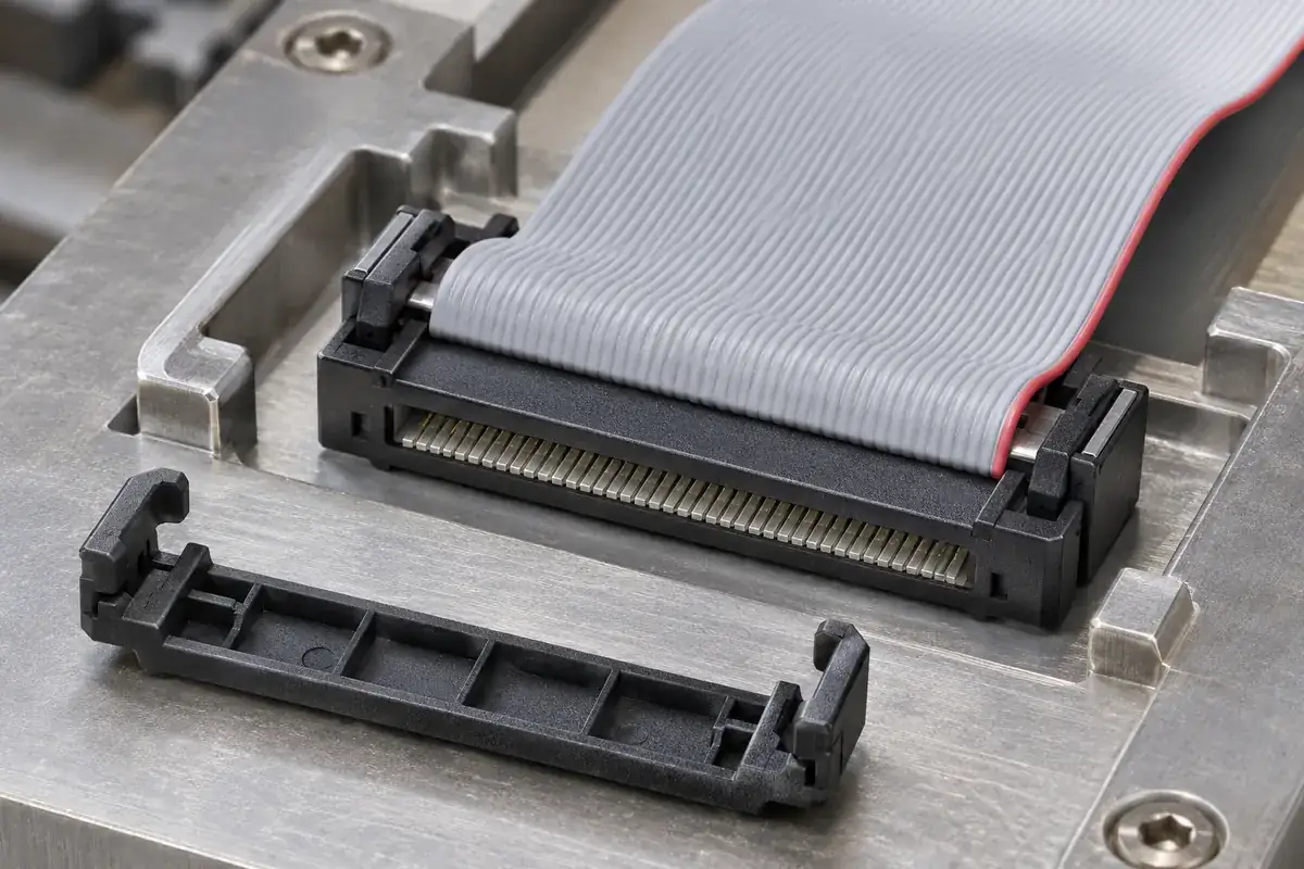
Keep unplugging and cable restraint distinct
A strain-relief bar should not automatically be treated as a pull handle. The 3M 891 Series pull-tab information describes a separate unplugging accessory. Follow the selected connector's handling instructions and provide an accessible grip or approved aid where the installed layout makes removal difficult.
During validation, distinguish cable retention, cover condition and electrical performance before and after the required handling. Record the configuration and direction of loading. A successful pull in one convenient direction does not establish every possible installation load. Test conditions should represent the actual assembly requirement and remain traceable to the approved component revisions.
For custom IDC housings, covers and restraint components, send the full cable route and surrounding clearance information with the plastic drawings. Include the intended handling method and the first external cable support. Those details help the molding review place useful support surfaces while keeping the termination and cable restraint responsibilities clear.