
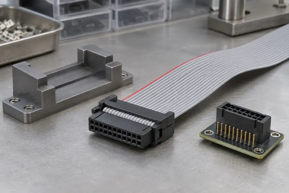
A closed IDC cover is easy to photograph, which can make it tempting to use that image as proof of a good connection. The photograph can show a visible assembly condition, but it cannot establish every conductor position or electrical requirement. A useful inspection plan separates the questions that can be answered visually from those that need dimensional, electrical or other specified evaluation.
That separation is particularly valuable when developing custom molded housings and covers. The plastic supplier, contact supplier and cable assembler may each control a different part of the finished result. Clear acceptance boundaries help the team investigate a failure without assuming that a neat molded part proves the termination or that an electrical fault must originate in the plastic.
Product design illustrations accompany the assembly and manufacturing explanations below.
Check the mechanical assembly state first
Begin with the defined component configuration. Confirm the housing, cover, contacts, cable and any strain-relief accessory against their controlled revisions. Similar-looking parts can differ in accommodation or assembly requirements. A correct inspection result has meaning only when the tested assembly can be connected to the actual drawing and bill of materials that it is meant to represent.
Visible closure checks can include the specified latch engagement, cover condition and absence of relevant damage. Inspect both ends where the design requires it. A single closed catch does not describe the entire cover, particularly if the part has tilted during pressing. Our one-sided latching article follows that failure mode and the tooling conditions that can produce it.
Dimensions should use the agreed assembly references and measurement state. The termination cover and a later strain-relief bar may produce different overall heights. A measurement taken from the wrong component can appear repeatable while evaluating the wrong function. Record what is installed and which surfaces define the measurement, rather than reporting an unexplained overall height.
The TE AMP MONO-SHAPE application specification separates assembly-height checks from inspection of the terminated wire. Its numerical requirements belong to that system. The broader inspection principle is to keep different observations distinct instead of treating one passing mechanical check as complete connection acceptance.
Verify cable placement and conductor assignment
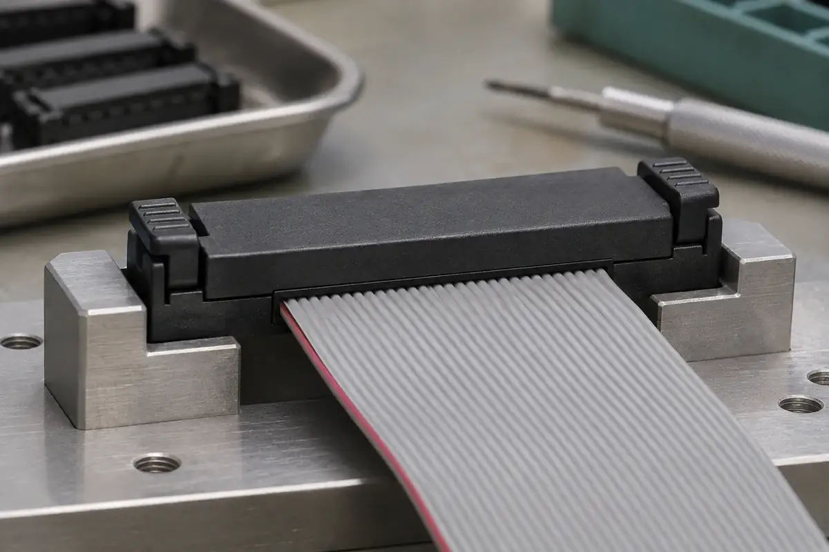
The cable should follow the intended route without riding over a guide, twisting beneath the cover or being pulled sideways by an unsupported tail. Some of these conditions are easiest to check before final closure. Define the inspection point while the relevant features remain visible. A final inspection cannot reliably reconstruct a hidden starting condition from the outside shape alone.
Conductor-one identification needs a controlled relationship to the connector view and electrical map. A red cable edge or a housing key provides a reference, but the assembly drawing defines what that reference means. Verify the map from the stated viewing direction so that a mirror-image interpretation is not repeated in both assembly and test-fixture design.
The IDC orientation guide explains how foldback routing can change the apparent side of an identified edge. Keep the underlying conductor assignment stable through those changes in viewpoint. An inspector should be able to distinguish a correctly folded cable from a reversed cable without guessing which photograph orientation the designer intended.
Cable position and electrical assignment are related but different. A perfectly centered cable can be reversed; a correctly oriented cable can be offset relative to the termination slots. The inspection plan should address both. This is another reason to specify the approved cable construction and contact pattern rather than relying on position count and a familiar connector outline.
Define the electrical question before selecting a test
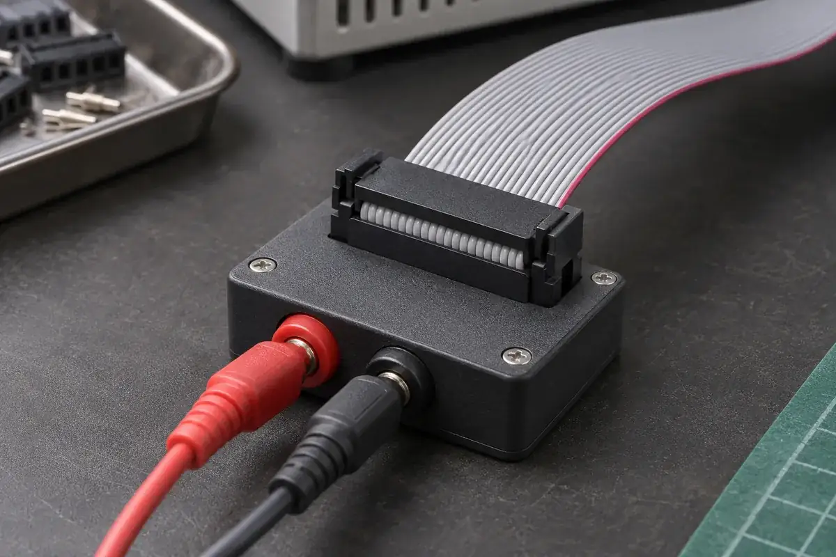
A continuity check can establish that a specified path exists under the selected test conditions. It should use the intended net list, including any required isolation between circuits. A tester that only confirms some connection at each end may miss a crossed or mirrored mapping. Verify the adapter definition independently so it does not reproduce the same drawing error as the assembly.
Contact resistance, insulation resistance, dielectric testing or other evaluations may be required by the selected product specification and application. These tests answer different questions and can require different equipment or preparation. Set the test voltages, resistance limits and sample quantities from the approved connector requirements. Record the method and fixture configuration so that a later result can be compared under the same conditions.
Where the application requires environmental or mechanical conditioning, identify whether electrical checks occur before, after or during that condition. A result from an unconditioned sample does not establish behavior after an unrelated exposure. Keep the tested state and the approved assembly configuration together in the record so the evidence is not later used beyond its original scope.
Destructive examination can help investigate a termination, but it also needs a defined method. Section location, preparation and sample selection affect what can be concluded. Preserve the connection between an observed feature and the specific contact, cable and tooling state. A useful investigation explains the inspected condition; it does not convert a single image into a universal performance claim.
Make the record useful when something changes
The inspection package should identify component revisions, cable lot or traceability reference, tooling configuration and the agreed acceptance criteria. Record actual results against those criteria rather than only a general pass statement. This information helps distinguish a molding change from a contact, cable or assembly-process change when a later batch behaves differently.
If a failure occurs, retain the relevant assembly state before rework. Opening the cover, pulling the cable or cycling the connector can remove evidence of the original problem. Follow the approved investigation and rework procedure. When a change is made, repeat the checks justified by that change rather than assuming that one corrected visual feature resolves every associated electrical concern.
For custom IDC plastic housings and covers, agree which molded-part inspections belong to the component supply and which finished-assembly tests belong to the connector program. Share the cable and contact drawings alongside the plastic requirements. That makes the quotation, sample review and production approval follow the same evidence chain instead of relying on a closed latch as the final verdict.