
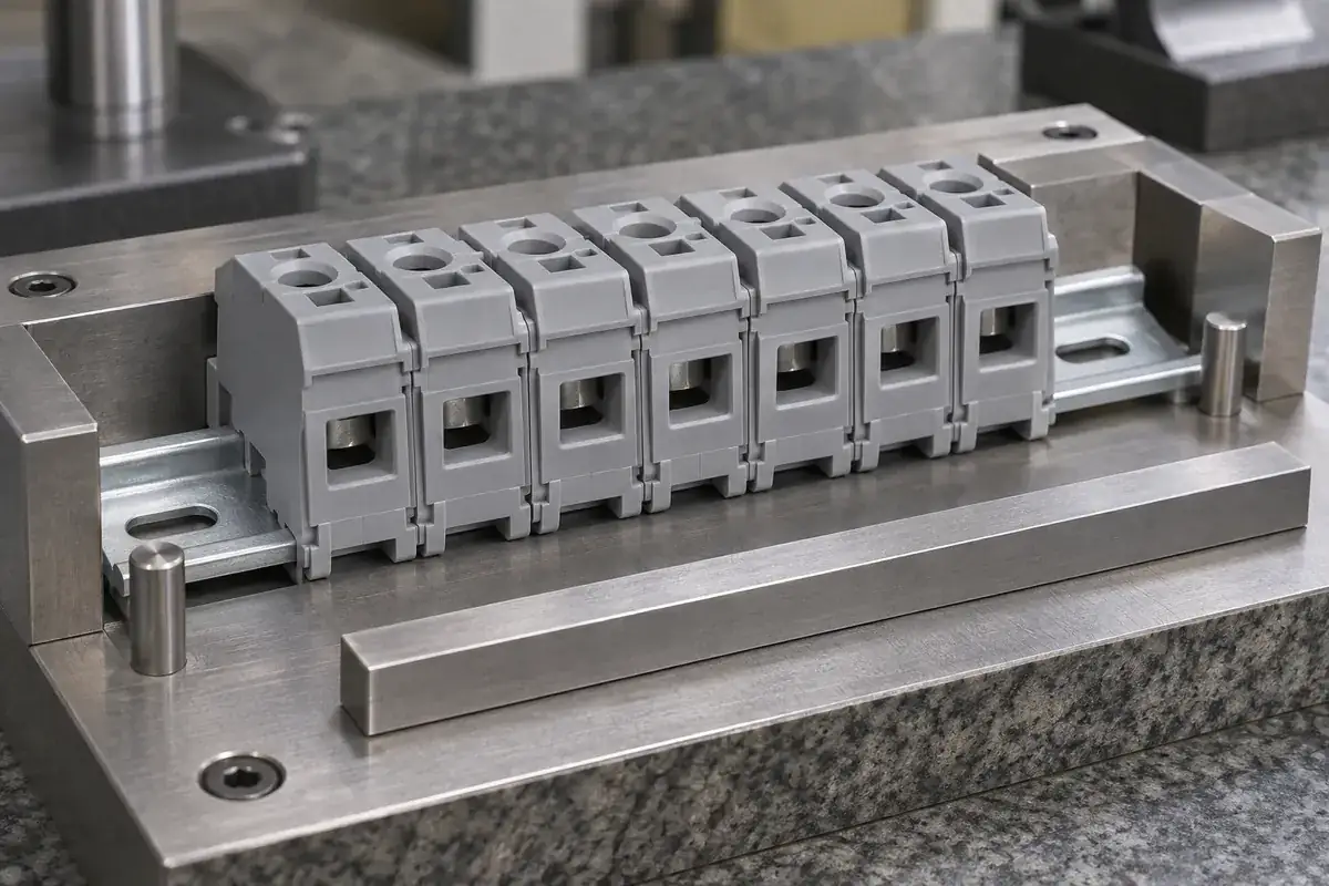
Two terminal block modules can join neatly, while a longer row gradually loses alignment with its board, cover or wiring openings. This is not necessarily a contradiction in the inspection results. An individual housing dimension and the final position of the last module answer different questions. Each repeated interface contributes to the assembled result.
For custom terminal block housings, define the longest relevant configuration before reviewing the molded part. A short demonstration row is useful for checking engagement, but it may hide the accumulated pitch variation or slight angular freedom that becomes visible in the actual product.
Product design illustrations accompany the assembly and manufacturing explanations below.
Decide what establishes the position of each module
In a rail-mounted row, the rail primarily locates the modules relative to its profile, while the neighboring side faces and joining features influence their spacing along the row. End restraints establish boundaries. These constraints can interact, but they should not be represented as a single generic dimension called alignment.
A PCB-mounted modular block has another reference: its pin pattern must relate to the board holes or pads. A housing joint may permit movement that helps assembly, yet that movement can also shift the last pin relative to the first. Identify whether the board, a fixture or the plastic joints establish the final spacing during soldering.
Phoenix Contact's SPT modular documentation describes configurable blocks using individual elements and specifies the resulting configuration. The practical lesson for a custom design is to document the assembled variant, not merely the existence of a module that can be repeated.
Separate pitch variation from play in the joint
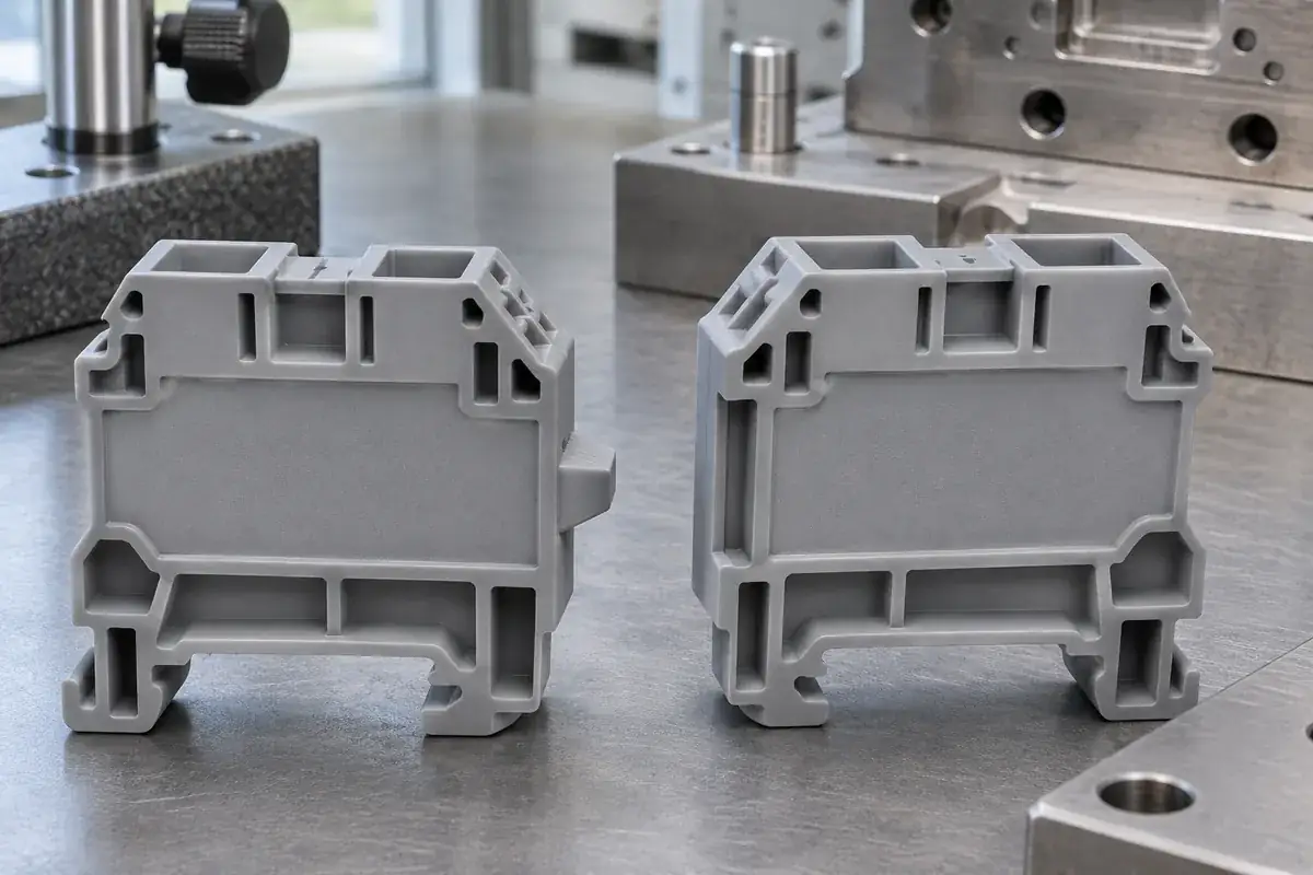
Pitch variation concerns the distance between corresponding features from one position to the next. Joint play concerns the movement still available after engagement. They may produce similar visible displacement, but different corrections are needed. Tightening a joint cannot fix a molded dimension that consistently makes each module too wide.
Equally, correcting nominal width may not remove a leaning row if the joint permits rotation. Look at angular freedom as well as translation. A small tilt at each connection can change the appearance of the top edge or the direction of the terminal apertures while the row length remains close to nominal.
Describe the assembly condition when measuring. Modules pushed together by a fixture can give a different row length from modules resting freely on a rail. Neither condition is automatically wrong, but the inspection must represent how the product is built and used. Record the restraint and seating method alongside the dimensions.
Use a tolerance model that matches the physical chain
Start at a meaningful datum and follow the chain to the feature that must align at the other end. Include repeated housing widths, joining clearances and any end components that enter the same chain. Avoid adding dimensions that do not actually control the location; a larger spreadsheet is not necessarily a more accurate model.
Determine which deviations can accumulate in the same direction. A conservative limit analysis can reveal whether the design has enough space even in an unfavorable combination. A statistical estimate needs justified process assumptions and evidence; it should not be used simply to make an uncomfortable maximum disappear.
Separate overall row length from local feature position. A row can meet its total length while one joint creates a local offset that obstructs a plug or cover. Where repeated apertures must line up, evaluate their positions relative to a common reference and not just the distance between the two outer faces.
Do not use the board to force a poor plastic fit
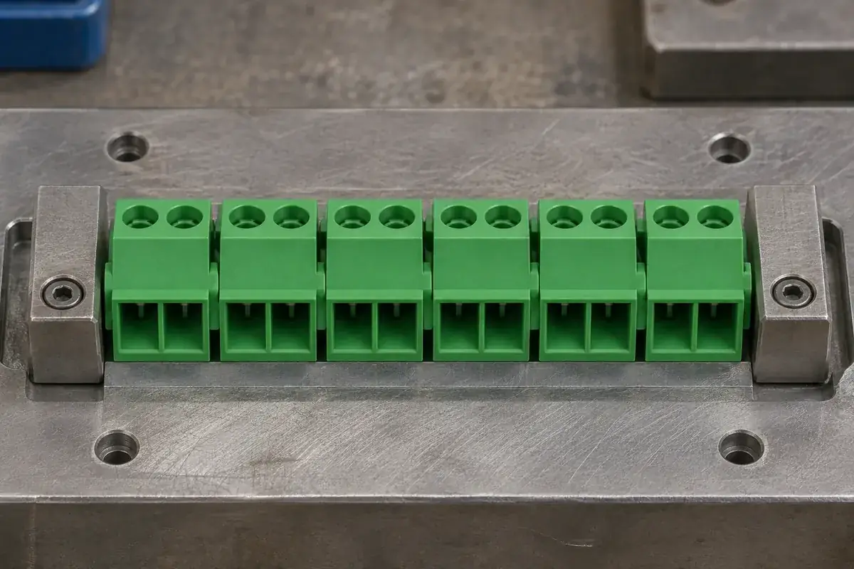
If pins enter the board only when the row is bent or squeezed, the assembly may be storing unwanted load. Enlarging board holes or increasing insertion force can conceal the symptom without explaining it. First check whether the housing joints, terminal locations and board pattern share the same reference system.
There can be legitimate reasons to allow controlled movement. It may help a modular row accommodate its mounting geometry. The useful distinction is between deliberate compliance with a defined range and uncontrolled looseness that varies between lots. Specify which features may move and which must remain positioned for the electrical and mechanical interfaces.
End clamps and covers also influence the practical result. A clamp placed under excessive compression can alter how joints seat; a cover may contact only the high point of a tilted module. Review these accessories in the intended order. The end plate discussion covers their separate closure and restraint roles.
Connect the inspection plan to the mold
In a multi-cavity tool, establish how cavity variation could appear in a mixed row. Measuring several parts from a single cavity does not show whether modules from different cavities assemble consistently. Ask for traceable sampling that lets the team distinguish a shared dimensional shift from a feature unique to one cavity.
The tooling review should identify the steel features controlling module width, joining geometry and terminal location. Discuss where an adjustment can be made without changing an unrelated fit. This makes the first trial more informative and avoids treating every assembly problem as a general shrinkage correction.
Validate the combinations that will actually be sold
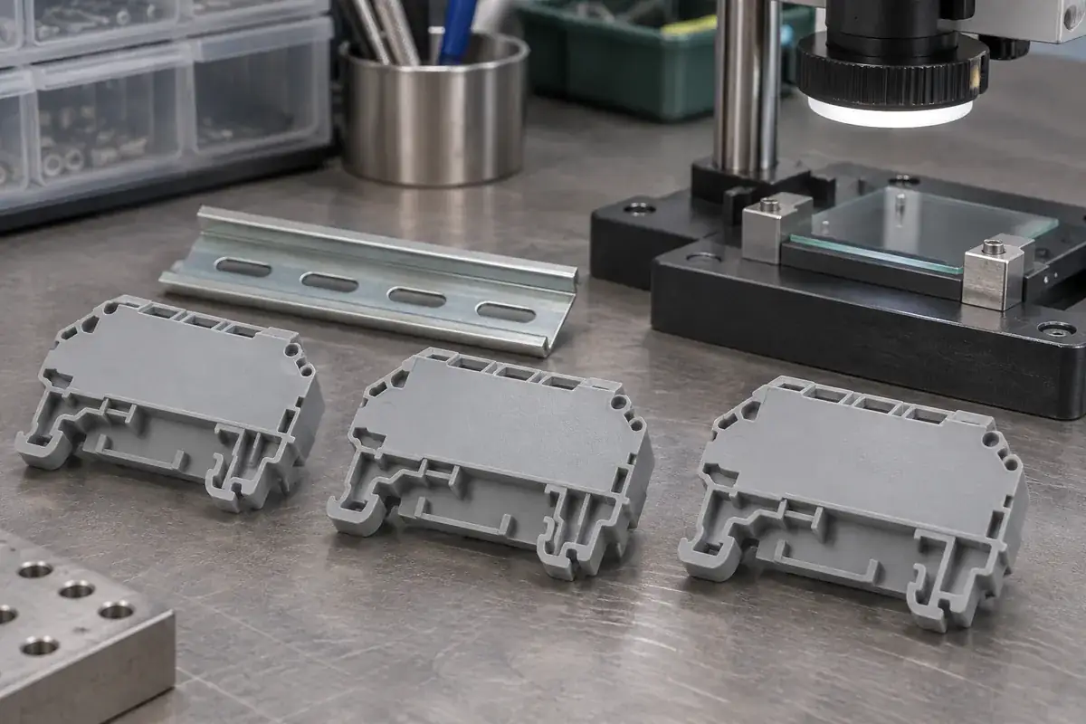
Include short and long rows, permitted module combinations and the intended end accessories in the validation scope. Where colors or materials differ, confirm whether those variants use the same dimensional acceptance basis. The appearance of a common product family does not prove that every manufacturing variation assembles identically.
Record the assembly sequence, fixture condition and measurement reference with each result. If a sample fails to seat, preserve its cavity identification and counterpart combination. A note saying that the row is tight gives little direction; a repeatable location and condition make it possible to isolate the responsible interface.
Bring these configuration details to the injection molding quotation alongside the component drawings. The commercial scope can then include the samples and inspection needed to assess a working modular row, rather than only a collection of individually acceptable plastic housings.