
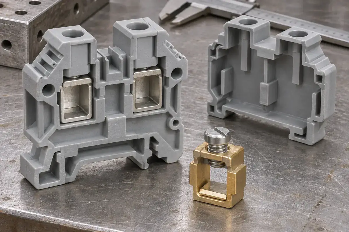
A metal clamp can fit inside a terminal-block housing and still be free to turn far enough to cause trouble. The wire entrance shifts away from the receiving pocket, the screw no longer sits beneath its access well, or a current bar approaches a neighboring boundary. Preventing that motion requires a defined interface between the insert and the plastic rather than a general instruction to hold the metal tightly.
Anti-rotation design is especially important when assembly and operation load a component differently. A retaining tab may keep an insert from falling out during handling but provide little resistance to turning. A broad flat may stop rotation effectively while allowing the clearance needed for insertion. Give each feature a clear role before combining them into one pocket.
Product design illustrations accompany the assembly and manufacturing explanations below.
Identify the direction and consequence of unwanted motion
Begin with the metal component in its intended final orientation. Determine which surfaces must align with wire openings, operating windows, adjacent conductors and mounting references. Then consider the rotation that would disturb those relationships. A small angular change can be harmless in one region yet move a narrow receiving opening enough to obstruct the prepared wire.
List the operations that can produce that motion. Tightening a screw can apply a turning reaction, wire insertion can push off-center, and moving an attached conductor can load the assembly after wiring. Component insertion into the shell may also twist the metal before it reaches its final seat. Review the sequence rather than assuming that one final-state fit controls every operation.
Distinguish rotation from translation and withdrawal. A pocket can resist turning while still allowing movement along its loading direction, which may be useful during assembly. Another feature then establishes the final stop or retention. Combining all three duties in a very small interference feature can make the component difficult to assemble and concentrate loads in a fragile area.
Prefer deliberate contact surfaces to accidental wedging
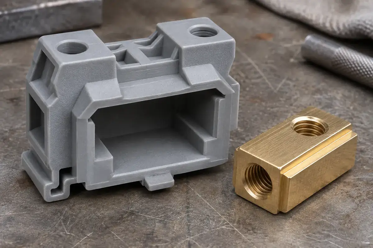
Broad opposing flats provide an understandable way to restrain a rectangular insert, but their clearance and location still need review. If one corner contacts first, the nominally broad support may act like a small point. Compare the actual metal shape, its edge condition and the molded pocket. The contact pattern should reflect the intended support rather than a hidden mismatch between rounded and sharp corners.
A key rib or tab can provide orientation when the insert otherwise has a symmetric outline. Position it where the metal can engage it predictably and where the plastic has adequate support. A thin isolated projection may be suitable for guiding assembly but unsuitable as the main reaction feature. Decide whether the key is an assembly guide, a stop or an operating-load interface.
Allow for the metal manufacturing process. Formed cages may have bend radii, stamped edges or slight asymmetry that are absent from a simplified envelope model. Define which surfaces are intended as functional references and which merely need clearance. The housing supplier needs that distinction to avoid locating the insert against an edge whose variation was never controlled for that purpose.
The Phoenix Contact PCB-terminal catalog illustrates the variety of connection constructions and their individual operating specifications. For a custom component, use the selected mechanism's drawings and requirements to establish the reaction interface. An anti-rotation detail from one terminal cannot be assumed suitable for a different cage or clamping arrangement.
Provide a workable assembly path
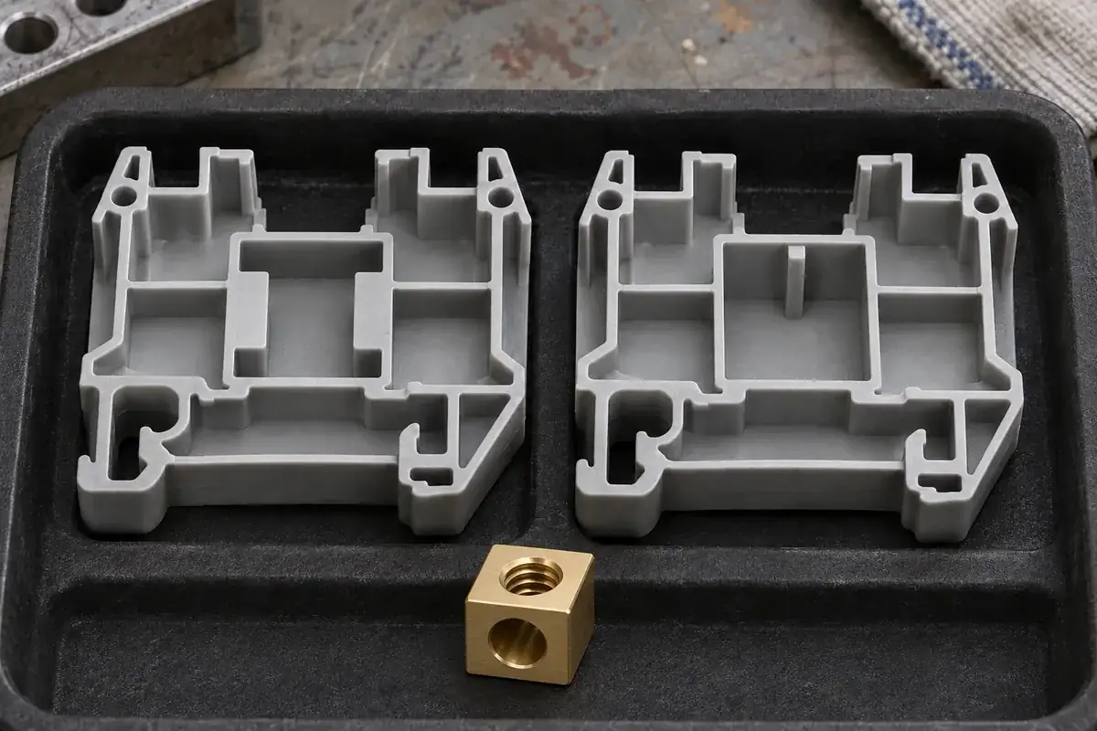
A strong final locating interface is useful only if the insert can reach it without damaging the shell. Follow the metal part from its initial entry to its seated position. Lead-ins can help align it, but the insert must not need to flex a wall beyond its intended movement or scrape through a feature that later provides the important reaction surface.
Consider the combined variation of metal and plastic along that path. A tight final fit may require a wider initial guide, while an undercut retainer may engage only after the insert reaches a controlled stop. Review those states independently. Treating the pocket as one uniform clearance can make assembly unnecessarily difficult or leave too much movement where orientation matters.
The assembly fixture should locate the shell without hiding a weak interface. If the fixture grips the metal and prevents it from turning during a trial, the molded anti-rotation feature is not being evaluated under the same condition it will see in use. Document which parts the fixture supports and release that support when the relevant operation requires it.
At this stage, connect the design with the terminal tightening load-path review. A flat that restrains rotation also receives a reaction, so its supporting plastic and nearby section transitions matter. Keep the force-carrying surfaces distinct from thin insulating walls wherever the construction allows, while preserving the required separation of conductive parts.
Control the interfaces that preserve orientation
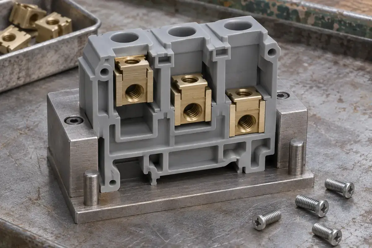
Dimensional inspection should use references connected to the operating relationship. The position of the locating pocket relative to the wire entrance and tool well is more useful than an isolated pocket width measured from an arbitrary outside surface. Define the functional datums with the metal and plastic drawing owners so both sides of the fit refer to the same assembly intent.
For sample evaluation, observe both seating and subsequent movement with identified metal inserts. Record the direction of any play and the surface that stops it. A simple statement that an insert feels tight does not explain whether the correct flat is engaged or whether the part is wedged at an unintended corner. Relate the observation to measurable interfaces.
If several metal variants will use one housing, compare their locating surfaces explicitly. Shared outer dimensions do not guarantee the same bend radii, key positions or reaction areas. The custom terminal block housing review should identify which variants are covered and which require a changed pocket, separate accessory or independent approval before production.
Carry the agreed interfaces through mold tooling development and injection molding sample approval. Preserve the relationship among insert orientation, tool access and wire guidance when considering draft, tool corrections or process adjustments. This gives anti-rotation geometry a concrete purpose that can be checked throughout the component's development.