
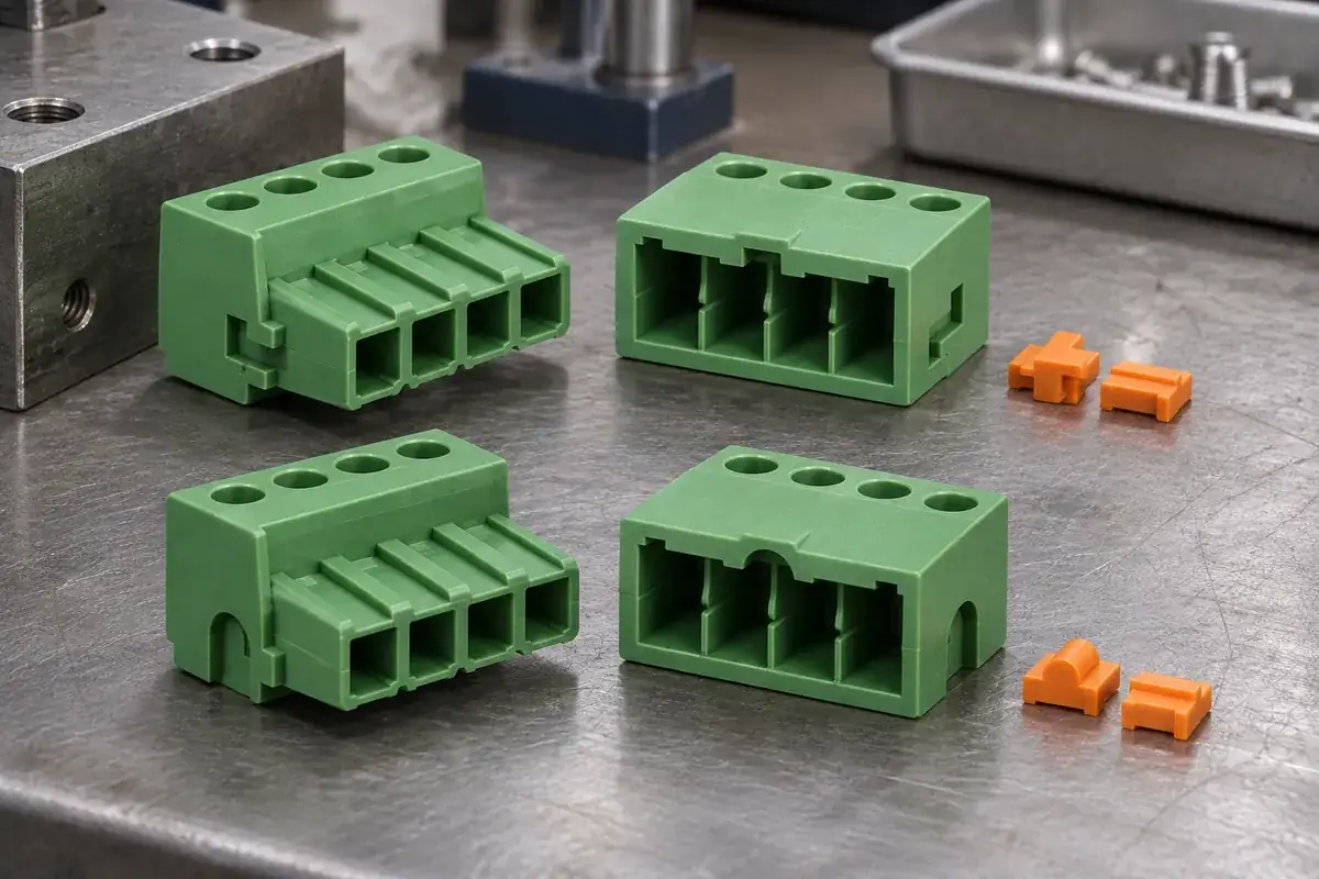
Two plugs with the same number of positions can look interchangeable even when they serve different circuits. Clear labels help an installer choose the intended connection, but a label does not physically prevent the wrong plug from entering a header. Mechanical coding adds a separate layer of control by changing which geometries can mate.
The strongest design review considers both mechanisms. Identification tells someone what the connection is; coding restricts the available mating combinations. For custom terminal block housings, define these roles before choosing a key shape or placing a marker recess on the plastic.
Product design illustrations accompany the assembly and manufacturing explanations below.
Map the possible wrong connections first
Start with the connectors that can physically reach each other in the actual equipment. Include harness length, service access and the possibility of adjacent units being opened together. A code plan based only on the electrical schematic can overlook two mechanically identical connectors that sit within easy reach of the same loose cable.
Consider orientation as a separate question from identity. Polarization can stop a plug being inserted upside down while still allowing it into the wrong circuit's header. Circuit coding should distinguish the combinations that must remain separate. Treating a single asymmetric outline as a complete solution can leave that second problem unresolved.
For a documented product example, Phoenix Contact's CP-MSTB coding profile is inserted into a dedicated slot on a plug or inverted header. That illustrates an accessory-based approach; the exact arrangement and permitted combinations remain specific to the chosen connector system.
Decide whether the code is molded in or installed later
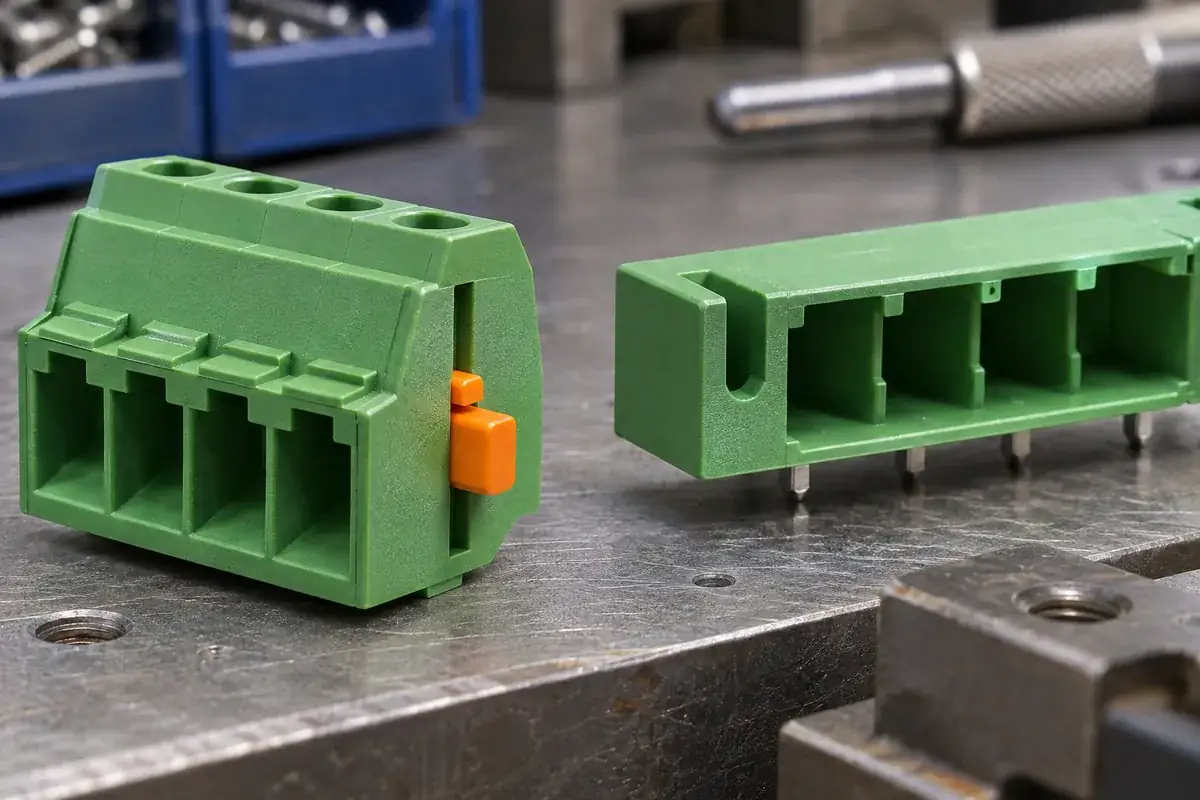
A molded key makes the identifying geometry part of the housing. This can simplify final assembly because no separate coding piece needs to be installed. The trade-off is variant management: different keys may require different tooling details, part numbers and stock separation. A change in the circuit plan can therefore become a plastic-part change.
A separate coding insert allows a shared housing to serve several configurations. It also introduces a small component whose presence, position and retention need control. A missing insert may remove the intended restriction. The assembly plan should make that omission detectable rather than assuming that an operator will notice the difference.
Removal and replacement need an explicit policy. If the insert can be transferred during service, explain who controls the code assignment and how the replacement is checked. If removal is not intended, do not imply easy field recoding merely because the part can be pried out with a tool.
Check rejection before electrical engagement
The important question is not only whether the wrong pair can fully latch. Determine how far it can travel before the coding features interfere, and compare that travel with the contact engagement sequence. A wrong plug that stops late may already have reached an undesirable intermediate condition.
Include realistic approaches to mating. A person may present the plug at a slight angle, start one end first or use the housing edges to guide insertion. Evaluate the permitted assembly motion with the actual metal contacts and surrounding components. A centered, straight CAD animation can miss a path available in the physical assembly.
Distinguish normal mating force from attempts to defeat a code. Define the misuse checks required by the product specification rather than inventing a universal force limit. Thin keys, local support and the flexibility of the main housing all influence whether the blocking feature remains effective in the relevant test.
Give labels a practical job
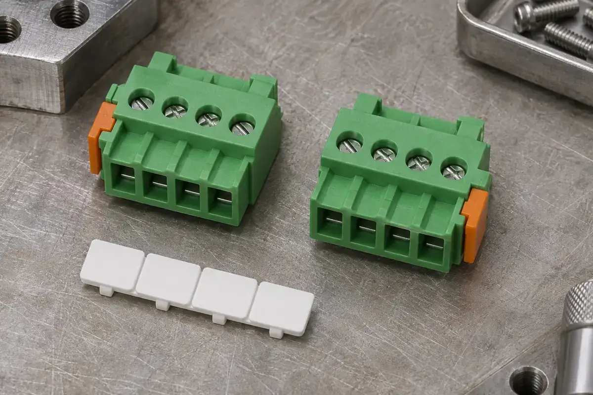
Labels still matter when the mechanical code is correct. They support installation, inspection and troubleshooting without repeated trial mating. Choose a marking location that remains visible after wiring and enclosure assembly. A large flat area hidden behind a cable bundle may be less useful than a smaller face oriented toward the service opening.
Review the marking method with the material and surface finish. A molded recess, clip-on marker or printed label creates different space and durability requirements. Keep the circuit identification scheme consistent between the plug, header location and documentation so that a correct physical match also makes sense to the person servicing it.
Color can reinforce identification, but avoid making it the only distinction. Lighting, contamination and similar shades can complicate visual recognition. A code assignment that also uses readable identification and controlled part numbers is easier to maintain when equipment is repaired or a supplier changes a permitted color formulation.
Include coding in manufacturing and change control
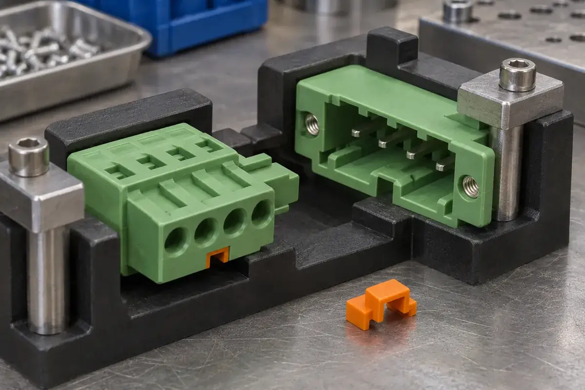
For separately installed inserts, define the assembly station and inspection method. Photographs of the intended configuration can help, but the acceptance basis should identify the actual occupied positions and component revisions. A finished connector should be traceable to the code scheme in force when it was built.
For molded variants, discuss the key geometry during mold tooling review. A small core feature may control rejection, while a nearby parting line or flash affects the allowed mating pair. Identify these functional surfaces so that tooling and inspection focus on more than the overall external dimensions.
Approve the code matrix, not only one good pair
Validation should demonstrate that each intended pair mates and each relevant prohibited pair is rejected under the defined conditions. Keep the matrix manageable by explaining which combinations are physically possible. Testing only one correctly coded pair proves little about cross-mating between the other variants.
Coding does not establish voltage suitability, conductor capacity or insulation compliance. Those depend on the complete terminal assembly and its qualification. The insulation geometry review addresses a different set of questions. Keeping the two scopes clear prevents a useful error-prevention feature from becoming an unsupported safety claim.
When requesting molded terminal block components, provide the mating models, variant matrix, marking requirements and expected service sequence. This lets the team compare molded keys with separate inserts on manufacturing effort, assembly control and future change needs.