
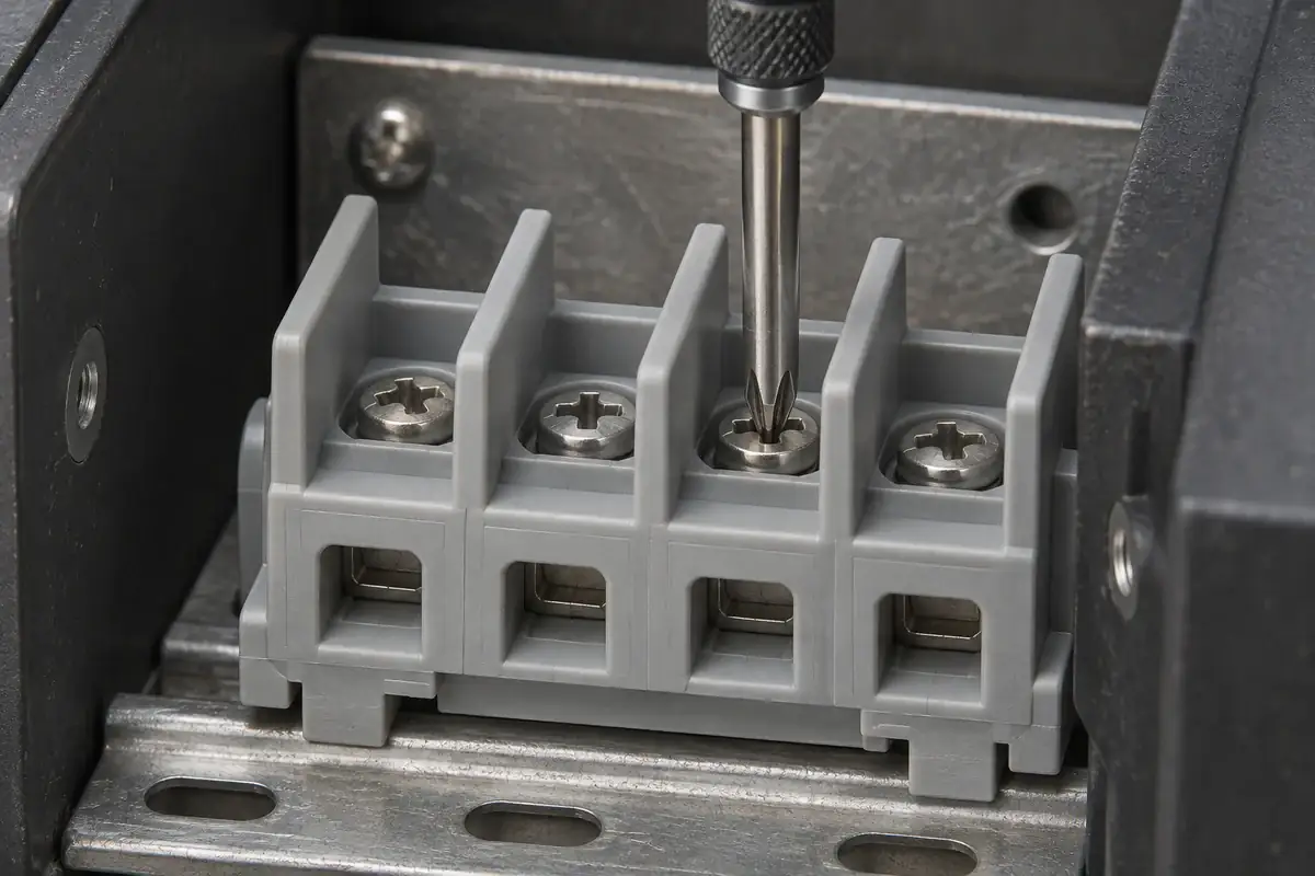
A terminal block may be easy to wire on an open bench and difficult to reach after it is installed. The screwdriver tip can enter the plastic opening, yet the wider shaft touches a divider or the handle meets an enclosure wall. Reviewing only the visible hole misses the full operating envelope and can turn a routine connection into an awkward, poorly aligned operation.
At the same time, the walls around that opening have a purpose. They locate the operating path and contribute to the protective arrangement around conductive parts. Improving access therefore requires a coordinated review of the driver, terminal mechanism, housing and surrounding equipment. Simply cutting away the nearest wall does not establish a workable final design.
Product design illustrations accompany the assembly and manufacturing explanations below.
Start at the mechanism and work outward
Identify what the tool is supposed to do. A screw terminal needs controlled engagement with the screw head and a suitable axis for tightening or loosening. A spring terminal may use a flat blade to move an actuator or open the clamp. These operations can require different directions, travel and contact surfaces even when the openings appear similar from above.
Phoenix Contact's connection-technology overview describes screwdriver operation for spring-cage terminals alongside other connection arrangements. The selected terminal's operating instructions should define the actual tool and action. Use those details to distinguish a screw-driving well, a spring-actuation slot and a test opening before developing the plastic geometry around them.
Once the contact point is clear, consider the tip, shaft, insulation sleeve and handle as one tool envelope. The tip may be the smallest part by a wide margin. A deep narrow well that accepts the blade can still prevent full engagement if a larger shoulder stops against the housing. Include the permitted tool design in the review rather than assuming every nominally similar screwdriver fits.
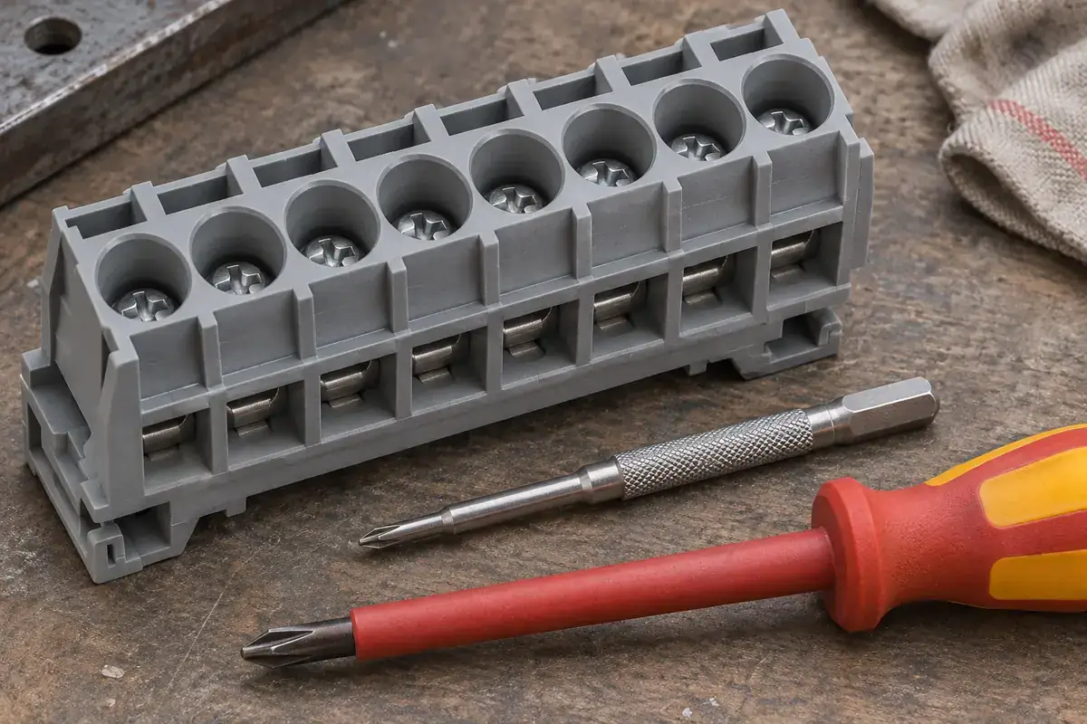
Test the path in the installed arrangement
Position the housing within its enclosure, board or terminal strip before checking access. Nearby partitions, cable ducts and covers can restrict the approach even when the housing's own opening is adequate. Start with the intended operating axis and examine whether the tool can reach it without first moving unrelated wiring or removing components that are meant to remain installed.
The permitted angle deserves explicit attention. A tool approaching at a steep angle may touch a molded lip before its tip fully engages the screw. An enlarged opening can improve clearance locally while leaving the handle obstructed farther away. Review the entire route from the equipment access point to the mechanism, including the space needed to withdraw the tool.
Include populated wires in that arrangement. A large conductor or ferrule collar at the adjacent position can block a tool that fits an empty terminal block. The relevant worst case may be the wiring sequence rather than the final arrangement alone: the last connection must remain accessible after the earlier wires are already in place.
Service operations can create another state. A release tool may need to remain engaged while the conductor is withdrawn, or the driver may need extra clearance to loosen a captive screw. Define the motions that happen together. Checking them separately can hide a conflict between the tool handle, the wire grip position and the surrounding wall.
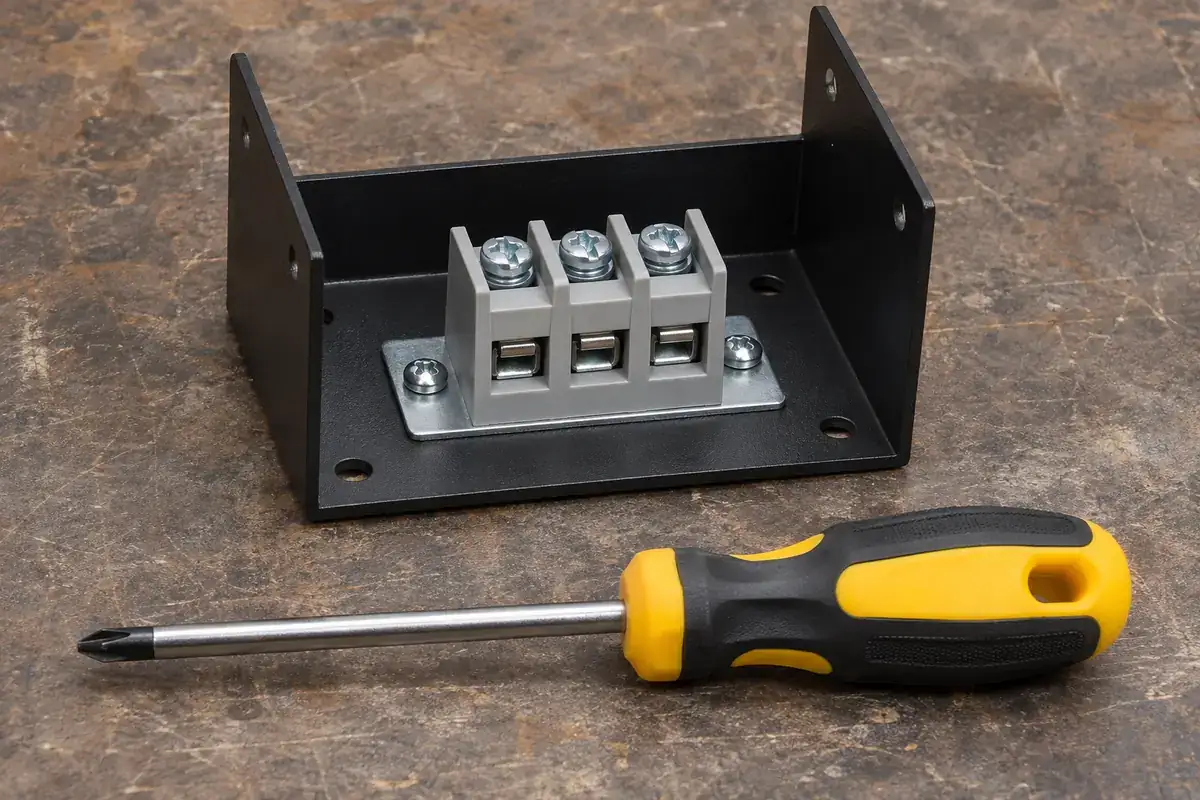
Preserve the function of the surrounding guards
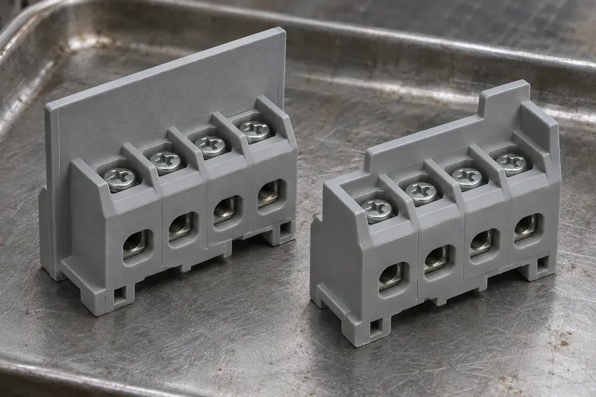
Review why each wall exists before changing it. An internal divider may separate neighboring conductive assemblies, while an outer wall may form part of the accessible boundary around the terminal. Other ribs locate an actuator or reinforce an opening. Their functions overlap, but they are not interchangeable, and removing one feature can affect more than operator comfort.
Wall height alone is not a complete measure of protection. The path around the wall, the shape of openings, the positions of conductive parts and the relevant accessibility evaluation all matter. The responsible electrical design team should define those requirements for the assembled configuration. Carry their critical boundaries into the plastic drawing so an access revision can be evaluated deliberately.
Sometimes the better change is outside the guard itself. Moving the terminal slightly, changing the tool approach through an enclosure aperture or adjusting a cable route may preserve the established insulating geometry. Compare those options before modifying a mold. The least disruptive housing change is not always the least expensive change to the complete product.
Where a molded revision is appropriate, the new shape must also be manufacturable. A tall thin lip, deep recess or sharp internal corner may complicate filling, ejection or dimensional control. Bring the functional access envelope into the mold tooling review so the toolmaker can discuss draft and support without losing the space the driver needs.
Approve an operation rather than a hole size
A practical review uses a de-energized assembly or a representative fixture with the specified tool and wire variants. Observe whether the tool reaches the intended engagement depth and whether its shaft bears against plastic during the motion. Record interference locations directly. This gives a proposed correction a physical target instead of a vague request for more clearance.
Measure the housing features that govern that operation from meaningful references. The location of a tool well relative to the clamp or screw matters more than its location relative to a cosmetic outer edge. Keep the counterpart assembly condition in the inspection plan, especially when the metal mechanism can move within its allowed clearance before mounting.
The review should also describe the supported service state: which covers are removed, which neighboring circuits are populated and which access points remain available. A design can be acceptable for assembly before final enclosure closure yet unsuitable for routine field rewiring. Establish the intended use so approval is based on the operation the product actually requires.
For custom terminal block housings, send the operating-tool definition and installation envelope with the component drawings. We can align the molded geometry with those interfaces during injection molding development. That preparation makes access, guard geometry and sample checks part of one review rather than separate late-stage corrections.