
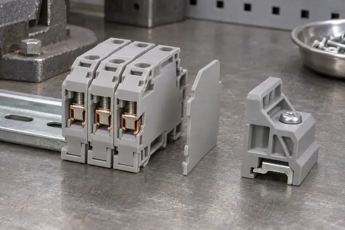
A terminal block row can look complete from the front while its outer side remains open. The repeated housings hide this issue in the middle of the row: one module sits beside another, and the assembled outline appears continuous. At the end, that neighboring wall is missing. The small plate used to close the side therefore deserves more attention than its size or price suggests.
For custom terminal block housings, review the end plate together with the housing and terminal arrangement. A plate selected after the main mold is finished may fit the visible perimeter yet leave a recessed area uncovered or interfere with assembly. Its location, retention and material belong in the component definition from the beginning.
Product design illustrations accompany the assembly and manufacturing explanations below.
Start with the open side, not the accessory name
Look at a section through the actual terminal assembly. Identify which conductive parts are exposed at the outer side, where the housing already supplies a wall, and where the adjacent module normally completes the enclosure. This separates a functional closure requirement from a cosmetic desire to make the row look tidy.
Not every terminal block uses the same construction. A fully enclosed housing may have different accessory needs from an open-sided modular design. Stepped modules, multiple levels and changes of profile can also introduce exposed transitions within a row. Review the selected combination rather than assuming that only the far right-hand end needs attention.
Manufacturer catalogs distinguish these accessories explicitly. Phoenix Contact lists end covers and rail end brackets separately, with their own dimensions and mounting descriptions. This provides a useful vocabulary for purchasing; it does not establish compatibility between a custom cover and a catalog terminal family.
An end plate and an end clamp solve different problems
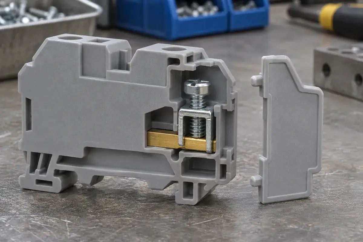
The end plate closes a side of the insulating structure. The rail end clamp restrains the row along its mounting rail. Depending on the assembly, both may sit next to each other and both may be plastic, but their geometry and load paths differ. A bulky clamp is not automatically a suitable substitute for a shaped insulating closure.
Conversely, a thin end plate should not quietly become the structural stop for a heavily loaded row. If the bracket bears on the plate, show the contact area and determine how that load reaches the housing. A narrow projection or unsupported region can be stressed even when the broad plate face looks secure.
Consider assembly order as well. Some plates attach before the module is placed on the rail; others are installed after the row is built. The chosen sequence determines access to the locating features and whether a technician can verify full seating. A plate that is easy to fit on an isolated sample may be awkward beside a cabinet wall.
Make closure repeatable across the whole perimeter
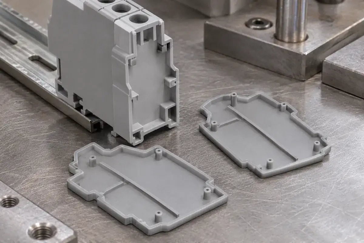
Flatness matters because a thin plate can touch at one corner while standing away elsewhere. Review the long edge, tall wall and attachment points together. A visual check from the front may miss the rear gap. Agree which views or sections demonstrate seating instead of relying on a single overall thickness measurement.
Locating pins and shallow ribs can help position the cover, but adding more of them is not always an improvement. Too many tight constraints can make the plate rock on mismatched features. Choose which features locate the part, which retain it and which simply support the perimeter after assembly.
For a snap attachment, consider the insertion direction and the deflection needed to engage. A latch that survives one laboratory fitting may behave differently after repeated removal or after conditioning. Define whether the plate is intended for routine service, occasional replacement or one-time assembly before evaluating the retention concept.
Review the assembled insulation geometry
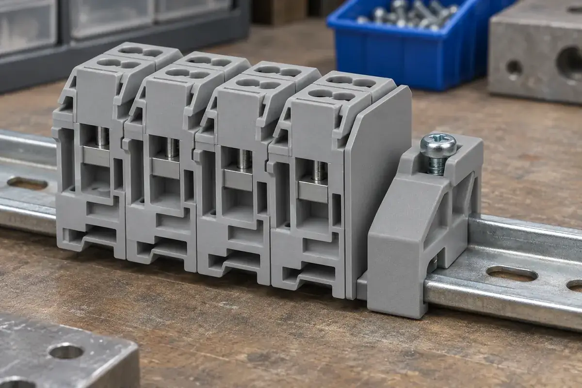
An outline match alone does not establish electrical suitability. The assembled cover can affect paths between a conductor, adjacent circuits and the mounting support. Its seam, apertures and local offsets need review within the actual configuration. Our discussion of terminal block barriers and insulation paths explains why a taller wall is not the whole assessment.
Include the metal parts in that review. A clamp cage or screw may occupy different positions over its operating travel. Evaluate the relevant positions specified by the product designer, not only the most recessed rendering. The plate should be judged against the defined conductor envelope and assembly requirements.
Material identity also needs to be specific. Matching the housing color does not demonstrate the same resin grade, tracking behavior or flammability classification. Record the proposed material and applicable evidence for the cover itself. Any final rating belongs to the qualified terminal assembly under its stated conditions, not to the appearance of a plastic accessory.
Thin parts still need a tooling conversation
A broad, thin plate can be sensitive to filling, cooling and ejection. During mold tooling review, discuss gate placement and how the part will be supported during release. Moving a gate to hide its vestige may change flow through a narrow retention feature or across a long edge that must remain flat.
Rib intersections and bosses deserve particular care because their local thickness differs from the surrounding plate. The objective is consistent support without creating avoidable distortion. Ask the molder to explain the relationship between the proposed tool layout and the seating surfaces, rather than treating all visible surfaces as equally critical.
Approve the plate as part of the row
Sample evaluation should include the intended housing revisions, terminal hardware, end bracket and rail. Check the accessible installation sequence and the assembled fit from both ends. If the row uses more than one module profile, include the transitions that the product actually permits. A successful fit on one isolated housing is useful but incomplete evidence.
Keep molded-part acceptance separate from assembly qualification. Dimensional and visual records can establish that the plate meets its drawing. They do not replace any required electrical or environmental assessment. This separation makes responsibilities clearer and helps purchasing compare a quotation for plastic parts with a proposal that includes assembled-system testing.
Send the plate and housing models together when requesting injection molding. Include the assembly sequence, required material, quantity and critical seating features. The resulting discussion can focus on a repeatable closure that fits the production process and the intended terminal configuration.