
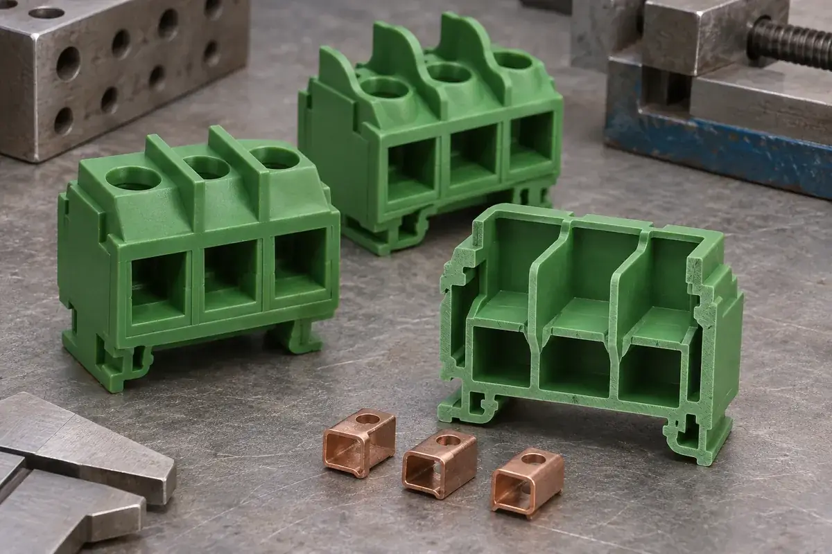
A taller plastic wall between two terminals looks like an obvious improvement to insulation. Sometimes changing the wall does help the relevant path, but its height alone cannot establish that a terminal block is suitable for a particular application. The shortest path may run around the end, beneath the housing or toward a metal mounting support.
When developing custom terminal block housings, the useful starting point is the complete assembly and its defined electrical conditions. Barrier geometry, material properties and test evidence contribute different information. Keeping them separate makes the design review more precise and prevents a resin property from being presented as a finished-product rating.
Product design illustrations accompany the assembly and manufacturing explanations below.
Clearance and creepage follow different routes
Clearance concerns separation through air. Creepage concerns a path along an insulating surface. A housing feature may influence both, but not in the same way. A deep surface feature may change a possible surface route while leaving another short air route available around an edge.
Phoenix Contact's electrical testing overview describes reviewing the shortest distances between adjacent terminals and between live metal parts and mounting supports. That assembly perspective is essential: the empty housing is not the full geometry that the electrical assessment must evaluate.
Identify the conductors and their relevant positions first. Screws, clamp cages, wire ends and accessories can change the occupied envelope. Include the positions and assembly states required by the product specification. A section showing only a nominal centered conductor can overlook a nearer edge in another permitted state.
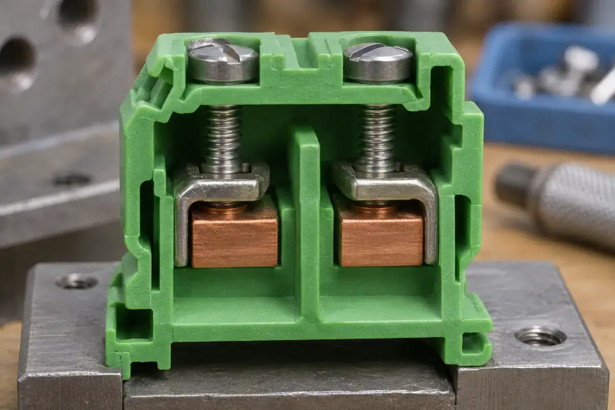
A barrier must be reviewed in three dimensions
A section through the middle of a housing is useful, but it does not reveal every route around the wall. Examine the barrier ends, openings for tools and the underside. Where two molded components meet, include the seam and the actual assembled offsets. The shortest relevant route may be outside the section chosen for the drawing.
Adding height can also interfere with wiring or tool access. If the resulting assembly requires a wire to bend awkwardly or a screwdriver to approach at an angle, the geometry has changed more than the insulation wall. Review the conductor insertion path and service envelope alongside the proposed barrier.
Grooves and ribs need evaluation under the applicable measurement rules. Do not assume every small contour adds its full drawn length to an accepted creepage path. The responsible designer or qualification team must determine how the geometry is assessed for the intended standard and conditions.
CTI describes a material test, not a connector rating
Comparative tracking index is used to compare insulating materials under a defined tracking test. UL's explanation of CTI testing describes it as an assessment of relative resistance to tracking. It is useful material information, but it is not the operating voltage of a custom terminal block.
Keep the exact resin grade and relevant material evidence with the design record. A general label such as polyamide does not identify a particular tracking result. Fillers, additives and formulation choices can distinguish grades within the same polymer family. Color alone is even less informative and should not be used to infer electrical properties.
A material's tracking behavior and its flammability classification answer different questions. Neither replaces the other, and neither by itself establishes the suitability of the assembled terminal. Purchasing should therefore request the specific evidence called for by the design, rather than accepting a collection of familiar abbreviations as an approval package.
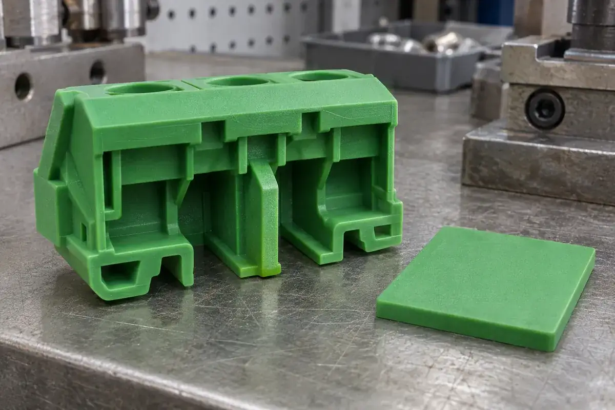
Choose requirements from the actual application
The required separations depend on the applicable product rules and the stated electrical and environmental conditions. Working voltage, expected transient conditions, pollution assumptions and other application factors need to be established by the responsible team. A universal table detached from those assumptions can create a misleading sense of certainty.
Record those assumptions where the mechanical design team can use them. If a barrier is critical to a defined path, identify the relevant surfaces and permissible geometry. A drawing note that merely says to meet electrical requirements leaves the mold designer guessing which local dimensions matter most.
Include the mounting arrangement and end accessories. An end plate, neighboring module or conductive rail can change the boundary under review. The terminal block end plate guide explains why the last module in a row deserves separate attention from the repeated interior modules.
Protect the important geometry through molding
Thin barriers need to fill and release consistently. During mold tooling review, discuss the steel forming the wall, local flow, venting and ejection. A visually attractive wall in CAD is not useful if the production process leaves an incompletely formed edge at a critical location.
Consider parting lines and permitted flash in relation to assembly. Flash can obstruct a metal component or prevent an end cover from seating, changing the geometry of the finished terminal. Specify functional acceptance at those interfaces rather than relying on a general cosmetic limit applied uniformly across the housing.
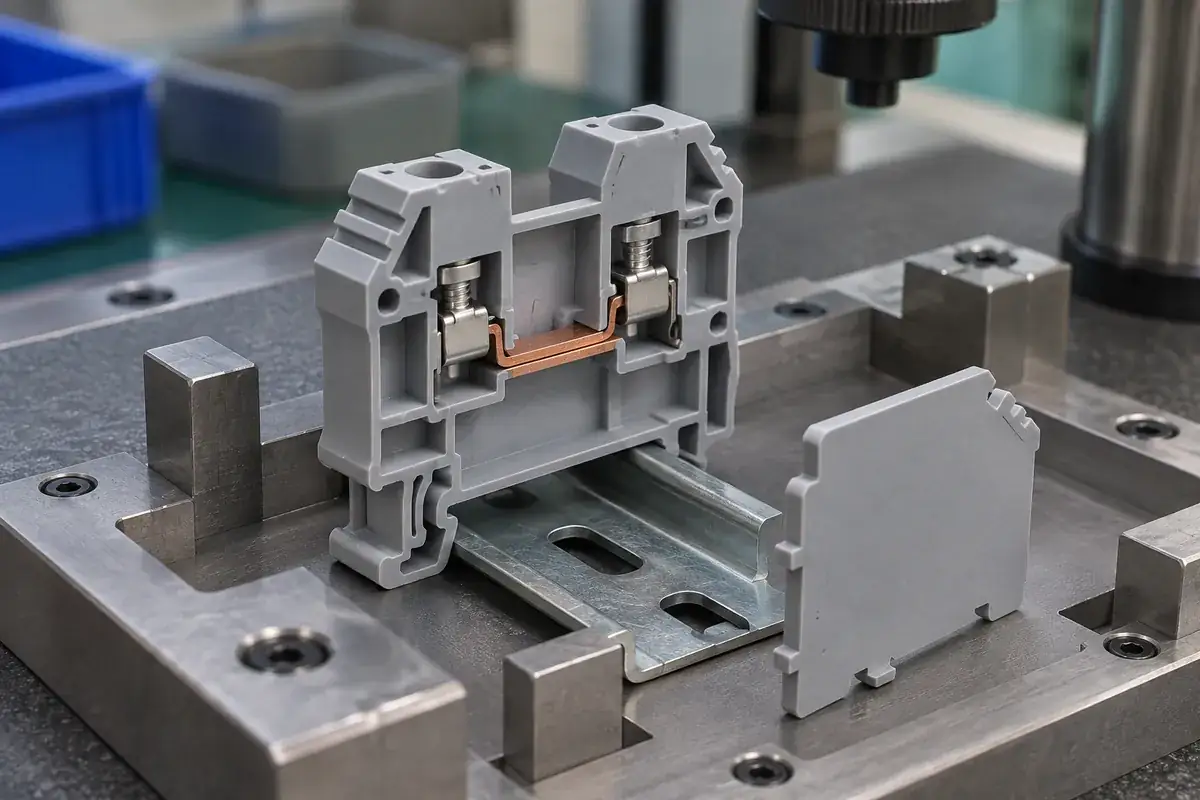
Separate part inspection from electrical qualification
Dimensional inspection can show that a molded barrier meets its drawing. Material records can establish which resin was processed. Assembly checks can show that the contacts and covers seat as intended. These are necessary inputs to a controlled product, but they should not be relabeled as completed electrical qualification.
Agree what testing and assessment the finished configuration requires, who performs it and which variants it covers. A change in material, terminal hardware or accessory configuration may need review even when the main housing outline is unchanged. Link any public rating to the actual qualified product and documented conditions.
For an injection molding quotation, provide the assembled model, proposed grade, critical surfaces and required inspection scope. That allows the manufacturing discussion to focus on consistently producing the defined insulation geometry while the product's electrical suitability remains supported by the appropriate assessment.