
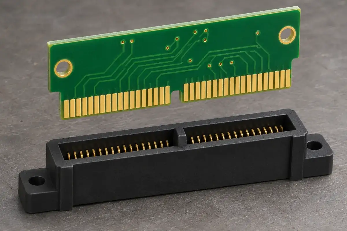
A polarizing notch is a mechanical feature, but its location cannot be chosen independently of the electrical interface. It removes part of the board edge and accepts a corresponding feature in the connector. Depending on the arrangement, that feature can occupy a contact position or sit between positions. A notch that fits the plastic may still conflict with the intended contact map.
The right review therefore starts with the complete interface definition. Put the board outline, contact fingers, circuit assignment and connector key on the same set of references. Then examine both the correct insertion and the incorrect conditions that the key is intended to stop. This is more informative than placing a notch wherever the layout happens to have visual space.
Product design illustrations accompany the interface and manufacturing explanations below.
Decide what the key must distinguish
Some keys distinguish the correct board orientation. Others distinguish different cards that otherwise share a connector format. Those are related but separate objectives. A symmetric notch may help center a board without reliably distinguishing its reversed orientation. Define the incorrect configurations before deciding whether a proposed key actually prevents them.
Include the relevant product variants in that definition. A key may reject one wrong card yet accept another with a wider or differently shaped cutout. Compare the physical interfaces for the intended family, rather than approving a key only against the single neighboring revision currently on the bench. The review should state which combinations are allowed.
EDAC's polarizing-key guidance distinguishes keys placed at contact positions from keys placed between contact positions. That distinction matters because a key can change the available contact arrangement. Use the chosen connector's drawings to establish the actual space and circuit consequences, rather than treating all keying options as functionally equivalent.
The key's purpose should remain clear in the drawing notes. A feature used to prevent incorrect insertion is not automatically an insertion-depth stop or a support for a heavy board. Assign those functions separately unless the design deliberately combines them. Otherwise, a later change made to improve one function can quietly weaken another.
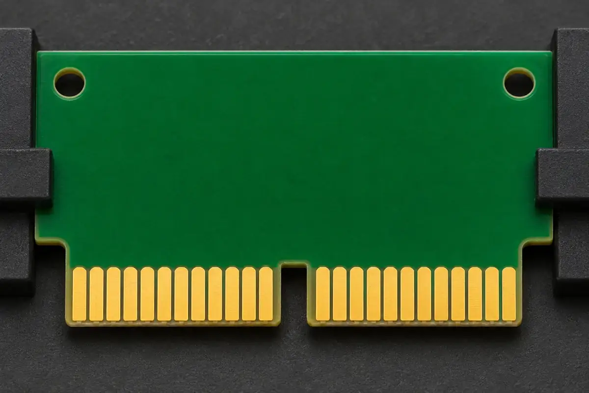
Reference the notch to functional board geometry
A notch location measured only from an unconstrained outer edge can be misleading if the contact pattern is controlled from a different reference. Consider how the board fabricator produces and inspects the outline and finger pattern. The dimensions should describe the relationship that the connector needs, including the permitted variation between those features.
The notch has a profile as well as a position. Its width, depth, corner geometry and edge condition determine how it passes the key. Review the full travel envelope rather than a top-view clearance alone. A corner that appears clear in a drawing can meet a molded radius or a key shoulder during insertion.
The key itself needs corresponding references in the plastic housing. Its position relative to the slot, contact cavities and mounting features affects the assembled relationship. A correctly molded key can still be in the wrong place for the board if the contact pattern is shifted within the same housing. Inspect those features as a connected arrangement.
For narrow molded keys, tooling access and support need to be reviewed early. A proposed rib may require a delicate steel feature or create a difficult fill region. Modifying the key to make molding easier should return to the interface review, because changes in thickness or corner shape can affect both correct insertion and rejection of a wrong board.
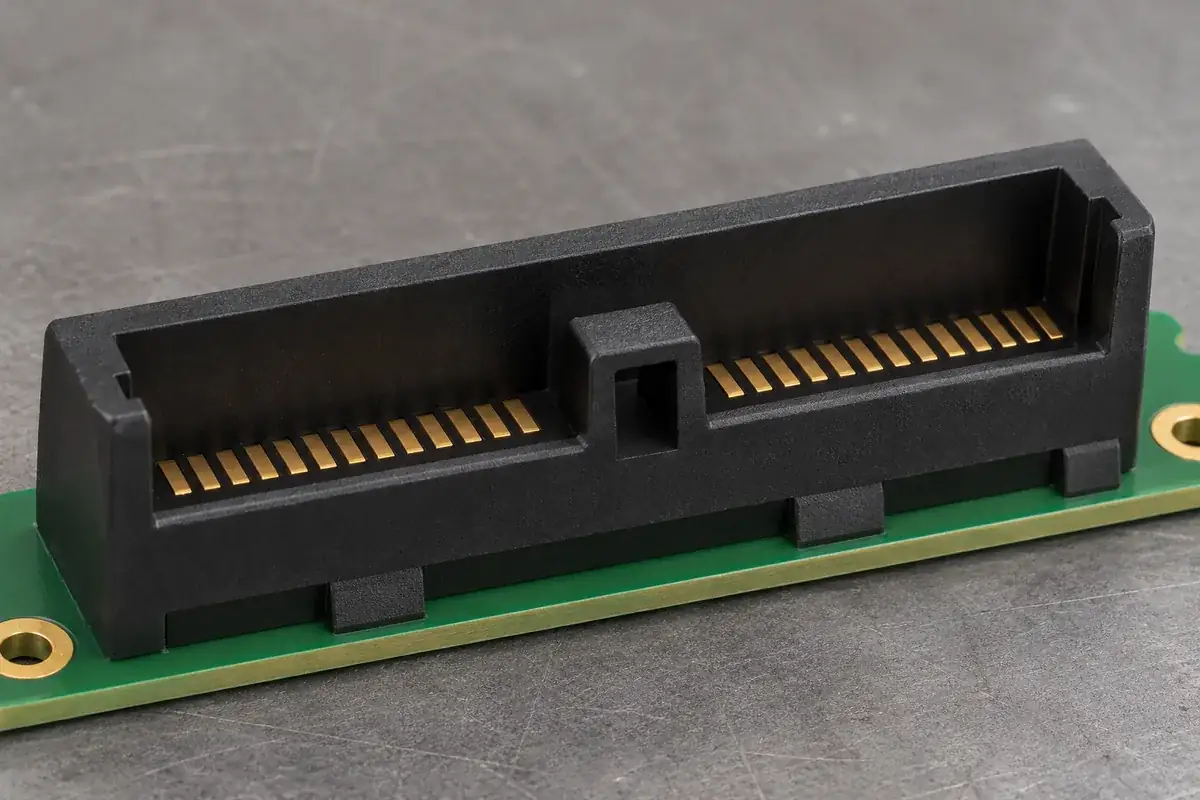
Examine the incorrect insertion before approving the correct one
A useful key stops an incorrect board before it reaches an unacceptable condition. Determine what touches first when the board is reversed or the wrong variant is offered. If the contacts can engage substantially before the key blocks further travel, the result may not meet the intended protection requirement even though full insertion is impossible.
Also consider how a person or assembly fixture can apply force. A key positioned under a long unsupported board edge may be loaded differently from one close to a guide. The review should consider the expected approach and handling conditions. Do not compensate for poor access by assuming the assembler will recognize and avoid every incorrect orientation.
At the same time, the key must allow the correct board to pass without relying on forced deflection. If a correct sample scrapes one side of the key, investigate the board outline, key position, guide location and approach angle. Removing material from the sample until it fits can obscure which controlled dimension actually needs to change.
Use clearly identified correct and incorrect interface samples when a verification plan calls for them. Record the board and housing revisions and define the observation required. A demonstration that one deliberately wrong coupon is rejected is useful evidence for that condition; it does not prove rejection of every conceivable card or establish an electrical safety rating.
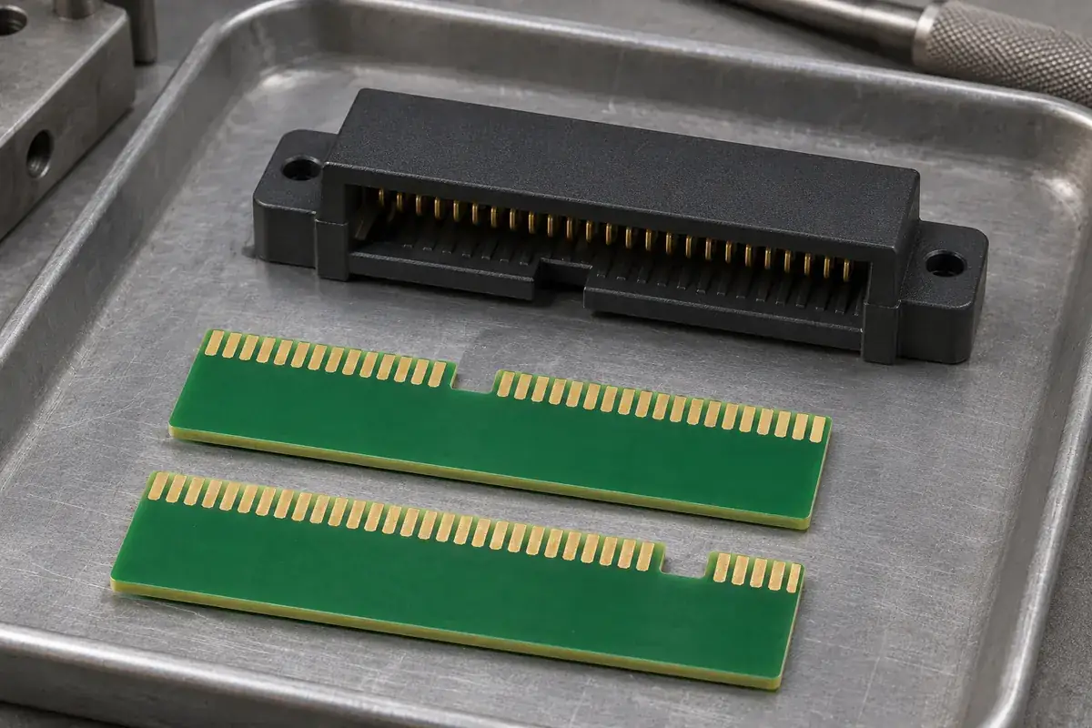
Keep keying separate from circuit identification
Mechanical keying and circuit numbering support different parts of assembly. A board can enter only one way and still have an incorrect circuit assignment. Maintain the contact map and inspection view alongside the mechanical definition. Our connector datum and pattern discussion provides a useful framework for relating pattern location to the part references.
The choice between open and closed housing ends can change how the board is laterally located. Revisit the key relationship when that structure changes. A feature that worked with end-wall location may behave differently when an open-ended socket relies on separate guides or another alignment mechanism.
Preserve the approved key definition through tooling and product revisions. Changes to the board outline, contact count or housing width should trigger an interface review, even if the key's nominal dimension has not changed. Track the permitted combinations explicitly so replacement parts and later product variants do not inherit an ambiguous fit assumption.
For custom card-edge housings, supply the board edge, contact pattern and keying intent together. Identify any contact positions reserved for mechanical features and the configurations that must be rejected. This lets the molding review address a defined function rather than adding a generic notch to an otherwise unfinished interface.