
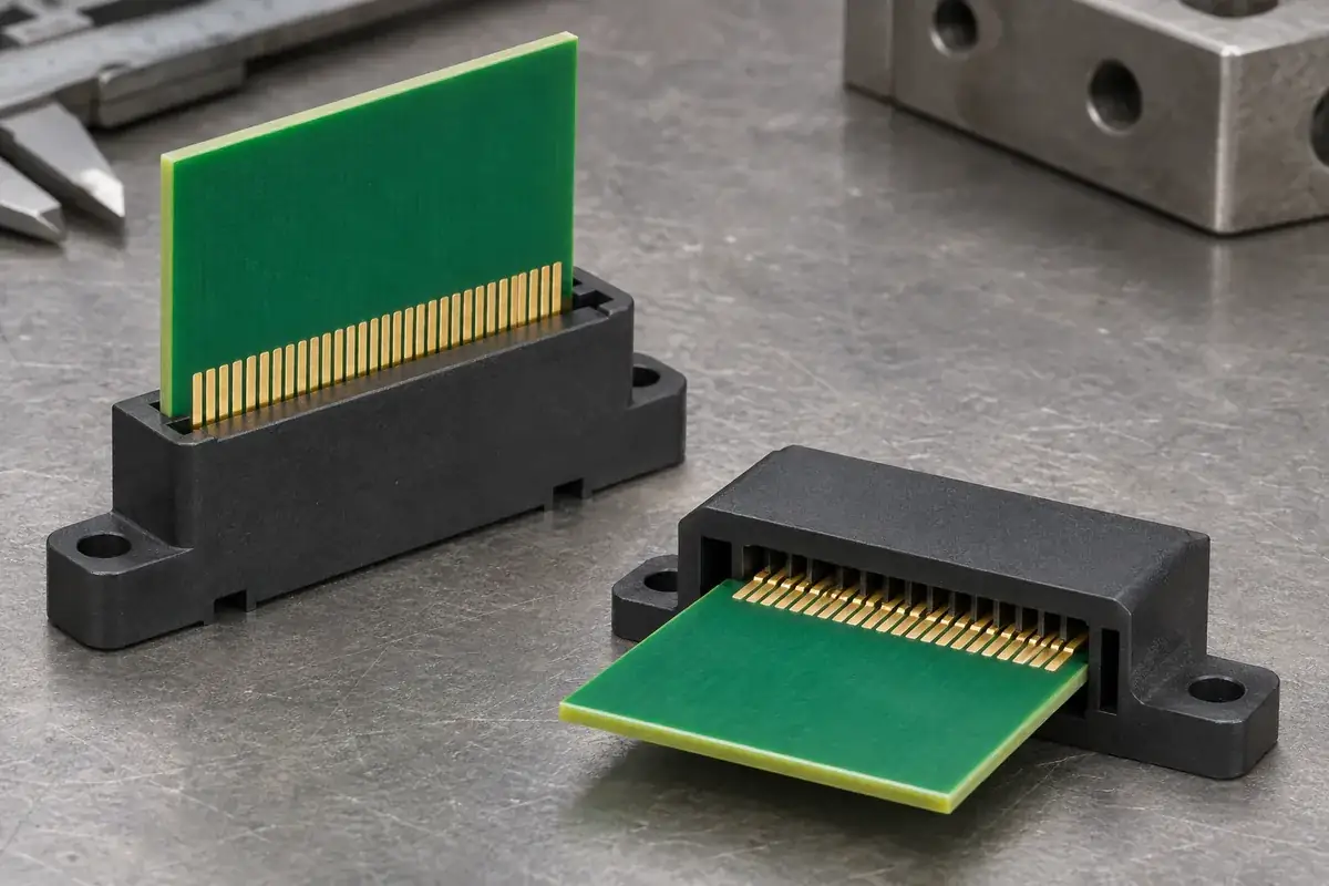
A connector orientation that saves space on the board can consume space during assembly or service. A vertical card may need clear travel above the socket, while a horizontal card can require a long approach beside the motherboard. Comparing only the installed connector outline misses the space needed to introduce, secure and remove the actual card.
Define the orientation relative to the mounting board before discussing the choice. Manufacturer terminology and product drawings identify the actual configuration; a photograph can be misleading when the assembly has been rotated. Then compare both layouts using the same card envelope, enclosure, guide arrangement and intended service procedure.
Product design illustrations accompany the interface and manufacturing explanations below.
Draw the whole approach envelope
The installed card position is only the end of its insertion path. The card needs space before it reaches the socket, including clearance for its components and any attached items. A layout that fits once assembled may be impossible to build in the intended order if a panel, bracket or neighboring board blocks that approach.
For an upright card, examine the space above and around the board. Guides can help establish the approach, but they also need an accessible entry. A tall component near the card edge may meet a guide or bracket before the contact fingers reach the socket. Include those features instead of using an empty rectangular board outline for every review.
For a horizontal arrangement, examine the space along the direction of travel and below the card. The board may pass over components or mounting features before seating. A short installed gap does not establish that the board can move through the approach without interference. Review the swept envelope rather than only the final cross-section.
Samtec's edge-card connector overview includes different mounting orientations and connector configurations. Those options illustrate why orientation is a system choice. The dimensions and mating requirements of the selected part remain the basis for the layout; one family's outline should not be used to represent another.
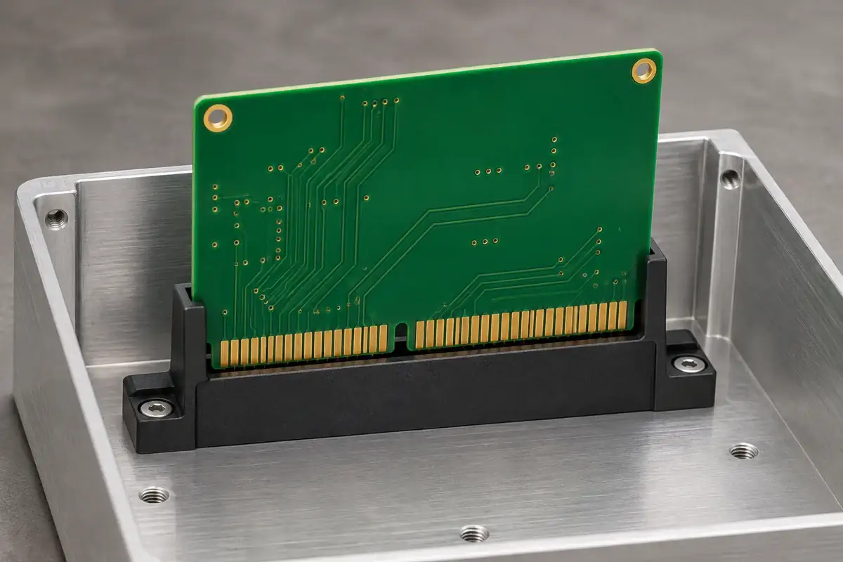
Compare guidance and support in each orientation
Orientation changes how the card is supported during the transition into the connector. A horizontal card may sag or rotate if introduced from one end without suitable guidance. An upright card may tilt laterally while its lower edge approaches the slot. Identify the support available at each stage rather than relying on the connector entrance to straighten the entire board.
The guide arrangement should lead to the connector's intended references. If a guide directs the board to a different center plane, additional insertion force will not correct the design relationship. Inspect the mounting and guide references together. This is particularly important when the guides are attached to the enclosure while the socket is located by the motherboard.
The installed support also differs from temporary insertion support. A bracket can secure the far end of a horizontal card after engagement, while an upright card may need a retaining feature that is accessed from another direction. Review how fastening that support affects the already-seated interface, including any movement introduced by tightening the hardware.
Electrical and mechanical acceptance still belong to the selected connector system. Changing orientation can change the available housing features, contact arrangement or termination configuration. It is not simply a matter of rotating an existing plastic model. Confirm the intended contact and mounting design before treating two layouts as equivalent manufacturing variants.
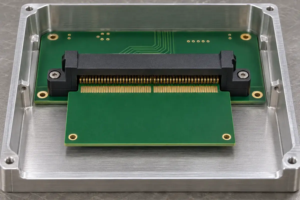
Consider access after the surrounding parts are installed
Service removal may occur in a more constrained assembly than initial production insertion. Cables, covers and adjacent modules may be added after the card is installed. Define which of those items can be removed during service and which must remain. Otherwise an apparently serviceable card may require an unintended level of equipment disassembly.
The person or fixture performing removal needs a way to apply force along the intended path. If only one corner of the card remains accessible, pulling can introduce an angle while the contacts are still engaged. Provide appropriate access and retention-release features in the overall design rather than assuming that the board will always be pulled evenly.
A retaining latch or bracket can add another access requirement. Its release motion may need space beside the card or beyond the connector end. Review that motion separately from the board travel. A card can have a clear extraction path while its retention feature remains inaccessible behind a wall or another component.
Use an assembly model that represents the service state, including the relevant fasteners and covers. A removed panel should be shown where it can actually be placed or accessed during the procedure. This helps identify whether the orientation choice improves real access or merely looks convenient in an isolated connector rendering.
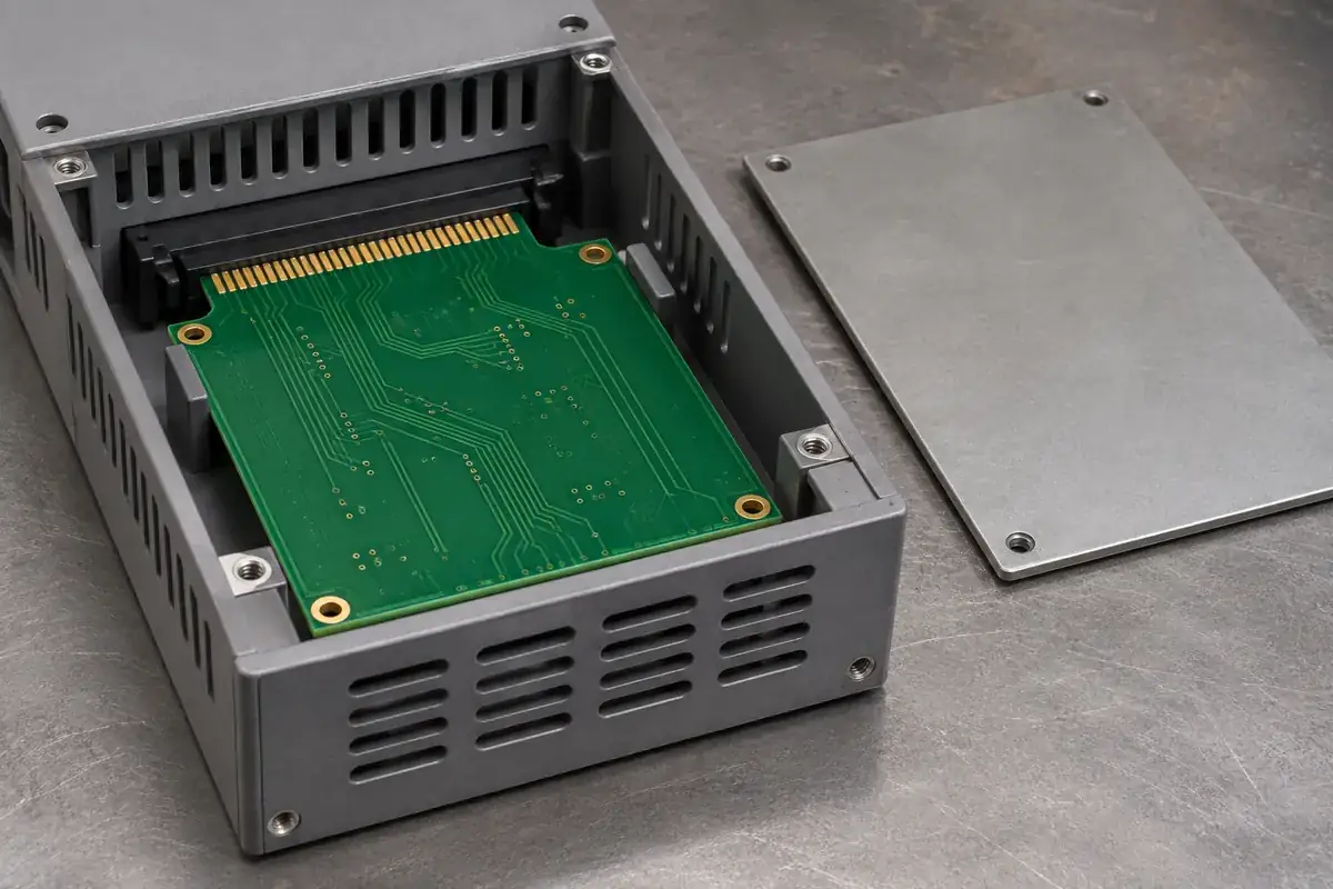
Carry the chosen layout into the housing requirements
The long-card support discussion explains why the connector and remote supports need a shared reference strategy. Apply that review to both candidate orientations. A layout that provides good access may still need a different bracket or guide arrangement to avoid loading the housing during use.
Keep the mating geometry and assembly envelope in the same revision set. The board thickness, edge finish and insertion-stop requirements remain relevant in either orientation. The board-thickness guide explains why a nominal slot fit does not establish the complete contact condition.
For the molded component, identify the surfaces used for mounting, guidance and handling. Review where gate vestige, flash or ejection marks could affect those functions. Orientation can make a previously accessible surface difficult to inspect or reach during assembly, so the inspection plan should follow the selected layout rather than an earlier concept.
When requesting custom card-edge connector housings, include the installed orientation and the insertion and removal paths. Provide the card envelope and surrounding keepouts with the plastic and contact drawings. These inputs allow tooling, sample evaluation and assembly responsibilities to be discussed around the real equipment configuration.