
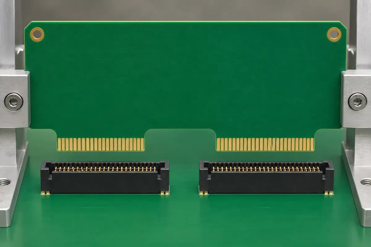
A card can fit each edge connector individually and still bind when both connectors are installed together. Each interface may be trying to establish a slightly different board position. The problem is then a relationship among the sockets, card features and supporting structure, rather than a simple defect in either plastic housing.
The first task is to describe how the assembly is meant to locate. Identify the references that control the card before contact, the features that establish its final position and any directions where accommodation is intentionally provided. Without that definition, tightening the tolerances of every component can add cost while leaving the conflicting reference scheme unchanged.
Product design illustrations accompany the interface and manufacturing explanations below.
Build one reference chain for the complete interface
Two separate groups of board fingers need a controlled relationship to one another. Their individual pitch can be correct while the distance or angle between the groups differs from the socket arrangement. Review the board pattern and outline as one system, including the fabrication references used to inspect the relative position of the groups.
The sockets likewise need a defined relationship on the motherboard or mounting structure. Placement features, mounting holes and the housing's internal contact locations all contribute. A pair of accurate outside housing dimensions does not establish that the internal mating regions are correctly positioned relative to the board fingers.
Consider the installed state after attachment. Soldering or fastening establishes the actual socket positions, and the surrounding structure may constrain the boards differently from a loose bench arrangement. Measure or evaluate the relationship in that state when it is the state relevant to mating. Otherwise an individual-component check may miss the condition that causes assembly difficulty.
The connector datum discussion provides a useful starting point for specifying those relationships. Extend the reference chain across both interfaces rather than creating two unrelated inspection plans. The goal is to make the measurements describe the condition the single mating card must satisfy.
Review which interface engages first
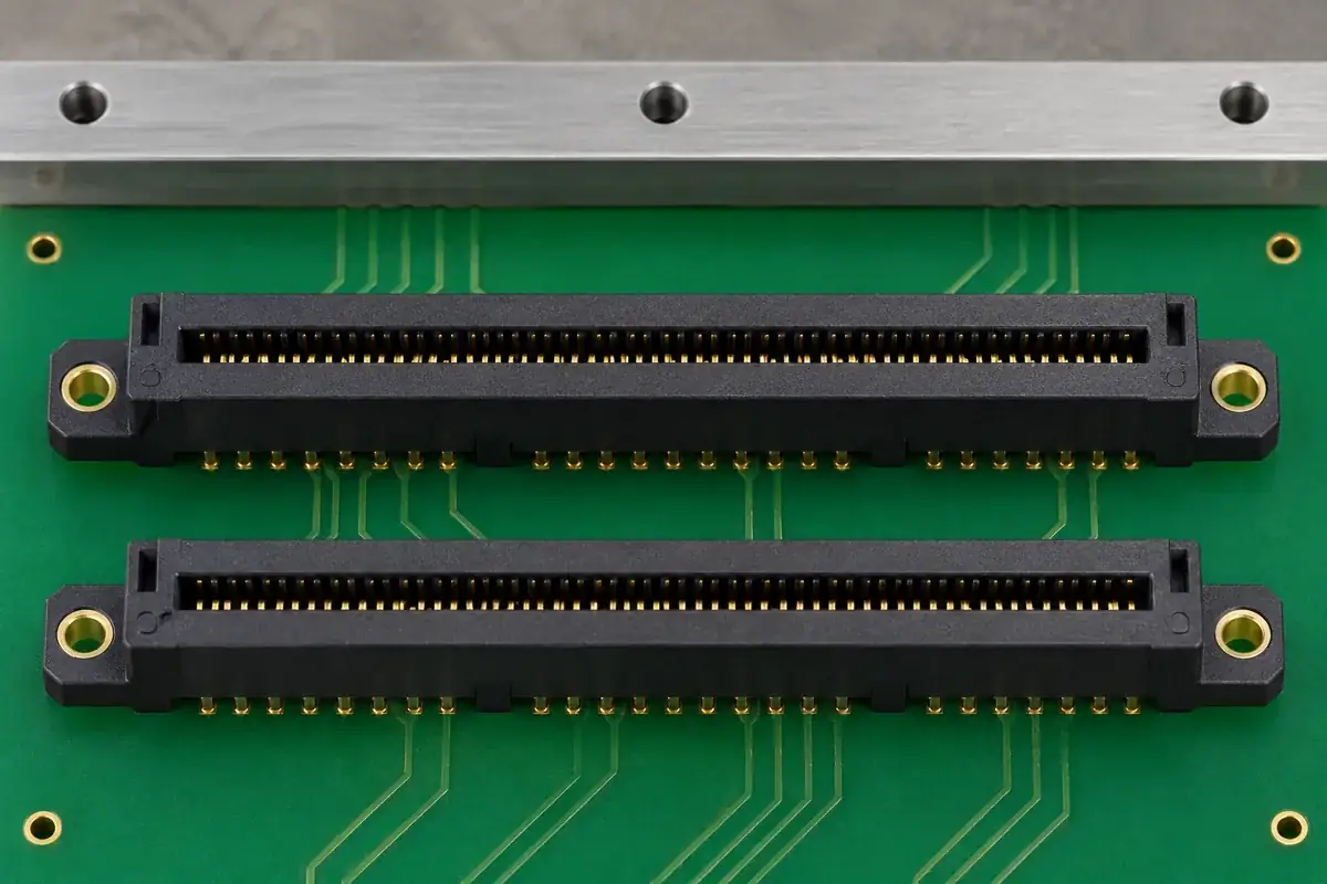
The card's approach may allow one group of fingers to enter before the other. That first engagement can constrain the board and change the path available to the second interface. Examine the full insertion sequence, including any height difference, approach angle or guide arrangement that makes the engagement order significant.
A guide can improve that approach, but it can also introduce another rigid requirement. If the guide path disagrees with the socket locations, the board may be forced against an entry lip or key. Review the guide references with both connectors installed rather than qualifying the guide against one socket at a time.
Samtec's MEC5 guidance recommends one socket with a higher contact count instead of using two or more MEC5 sockets for the same card: their alignment beams can oppose one another. Resolve that family-specific restriction before attempting a multiple-interface layout. For other selected connector systems, confirm the permitted arrangement with the manufacturer and identify how each socket locates the card. An ordinary molded slot does not provide the alignment behavior of a specialized connector mechanism.
Keep the board's stiffness and support condition in the review. A long or wide card may bend enough to make an imperfect approach appear possible, but that deflection can leave loads in the installed assembly. An easy hand insertion is not proof that the reference scheme is sound when the board is later secured by its brackets or enclosure.
Distinguish designed accommodation from uncontrolled looseness
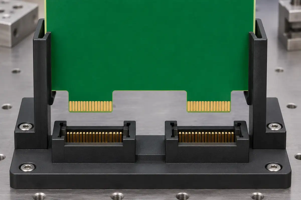
Some assemblies deliberately allow movement in a defined part of the interface. That accommodation may be provided by a selected connector system or a designed mounting arrangement. Its direction, available travel and load behavior must be part of the design definition. A loose fastener or an enlarged hole does not automatically create a suitable floating interface.
If one feature establishes the primary location, identify what the other features must permit. The arrangement should still preserve the required contact engagement, keying and installed support. Review the allowed movement against the electrical and mechanical requirements rather than choosing a clearance solely because a difficult prototype then becomes easier to assemble.
Changing a custom plastic housing can affect more than the board's lateral freedom. A wider slot or shorter key may alter guidance, protection or the contact-support geometry. Assess the proposed change with the complete connector definition. The molding supplier should not be asked to remove a functional feature without knowing what responsibility it had in the assembly.
A practical investigation separates the interfaces without losing the reference conditions. Compare each socket individually, then both together using the intended fixture. Observe where the sequence changes and which surfaces first touch. This can help identify a conflicting location, but final approval must still use the complete intended arrangement.
Verify the combined assembly before releasing the housing
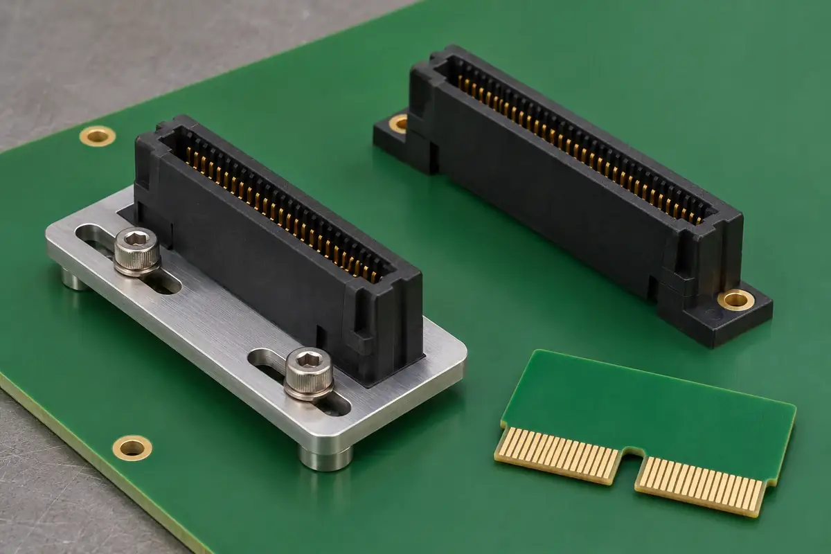
Use a board or coupon that represents the relationship between the separate finger groups. Two independent single-interface coupons cannot demonstrate that one rigid card will fit both sockets simultaneously. The fit-coupon guide explains why a sample must preserve the features relevant to the actual question.
Include the final supports and fastening sequence in the sample review. A remote bracket can pull a previously free card into a conflicting position after both connectors engage. The long-card support discussion covers that load path. Observe the condition before and after fastening instead of evaluating only the moment of insertion.
Document the board revision, connector revisions, mounting references and any intentional adjustment used during the trial. If an assembler must shift one component to achieve fit, that action needs an approved place in the process or a design correction. It should not disappear from the record when the sample is described as successfully assembled.
For custom card-edge connector housings, provide the complete multi-interface layout with the plastic and contact drawings. Identify the main locating features, insertion sequence and any intended accommodation. This allows the housing tooling and inspection plan to support the real assembly, rather than optimizing each socket in isolation.