
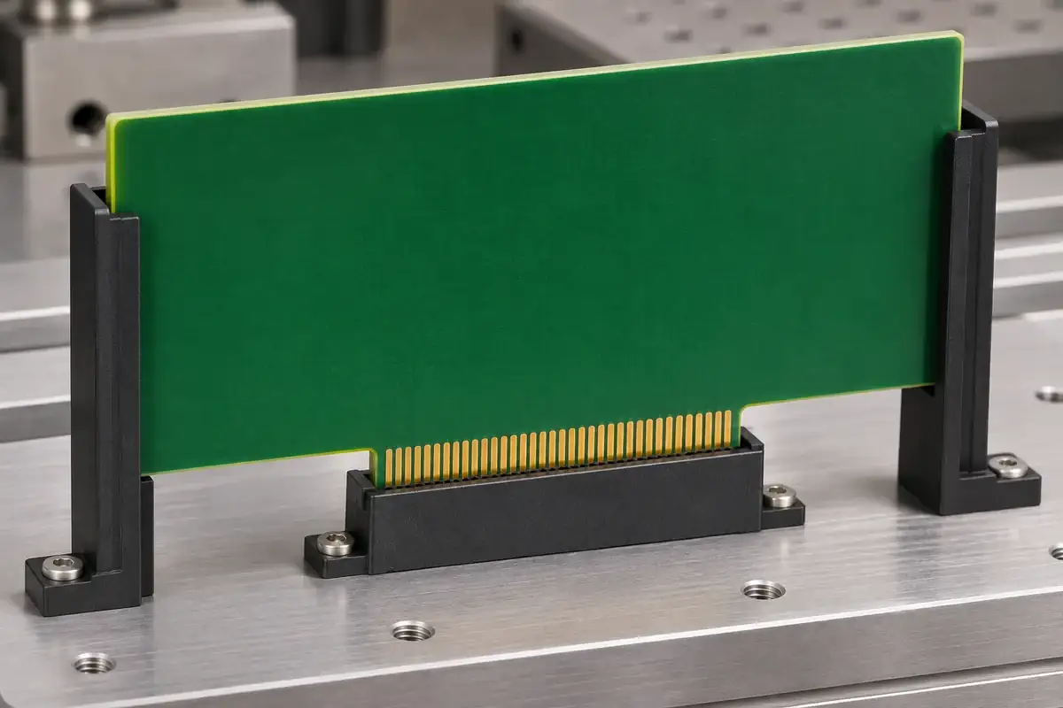
A long circuit board gives a small card-edge connector a large mechanical problem if the surrounding assembly provides little support. A force applied near the far end of the board can create a moment at the connector. The resulting movement may involve the housing, contacts, solder joints or mounting structure, and tightening the slot is rarely a complete answer.
Support needs to be considered across the whole sequence: approaching the connector, entering it, securing the board and removing it later. A bracket that works well after installation may offer no help during insertion. Conversely, a guide that makes insertion easier can create a conflicting location once the card reaches its final mounting points.
Product design illustrations accompany the interface and manufacturing explanations below.
Separate guidance from installed support
A card guide controls the approach along a defined path. It can reduce the opportunity for the board to arrive at the slot with an unintended angle. Installed support has a different task: reacting the specified loads when the card is in service. One feature can contribute to both, but those functions should be reviewed and verified separately.
EDAC's card-guide information describes guides used to align a card with a connector slot and offers different guide arrangements. That supports treating guidance as an explicit part of the interface. It does not establish a structural load capacity for an unspecified guide, bracket or custom housing.
Consider where the guide first captures the board. If it starts close to the socket, much of a long card can remain uncontrolled during the early approach. Extending guidance can improve that stage but requires space and an appropriate board-edge definition. The guide should act on a region that is intended to tolerate contact with it.
The guide clearance must also suit the card's permitted thickness and shape. A tight channel may appear to stabilize the board while making the assembly sensitive to bow, edge variation or fixture position. Review the guiding condition with representative boards and the actual mounting references, rather than selecting a clearance solely to remove visible movement.
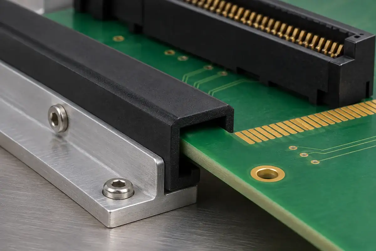
Trace the force path through the assembly
During insertion, the applied force should reach the intended contact interface through a supported card and a controlled approach. If the assembler pushes on an unsupported corner, the board may twist before entering the socket. A housing lip can then become an unintended lever point. Review the insertion method alongside the location of the guides.
After installation, external loads may come from attached cables, adjacent hardware or the equipment's specified service environment. Identify those loads and where they enter the board. The connector's electrical function should not be treated as evidence that it can act as the sole mechanical anchor for every load on a long assembly.
A remote bracket can shorten the unsupported span, but its attachment must be coordinated with the connector location. If fastening the bracket pulls the board away from its natural seated position, the support has introduced a new load. Evaluate the assembly before and after fastening to understand what the support is actually doing.
The molded housing also needs clear responsibility. It may include mounting ears, guide interfaces or local support lands, but those features require drawing-defined geometry and acceptance conditions. Adding a rib without understanding the force path can move a weak point elsewhere rather than resolve the underlying mechanical requirement.
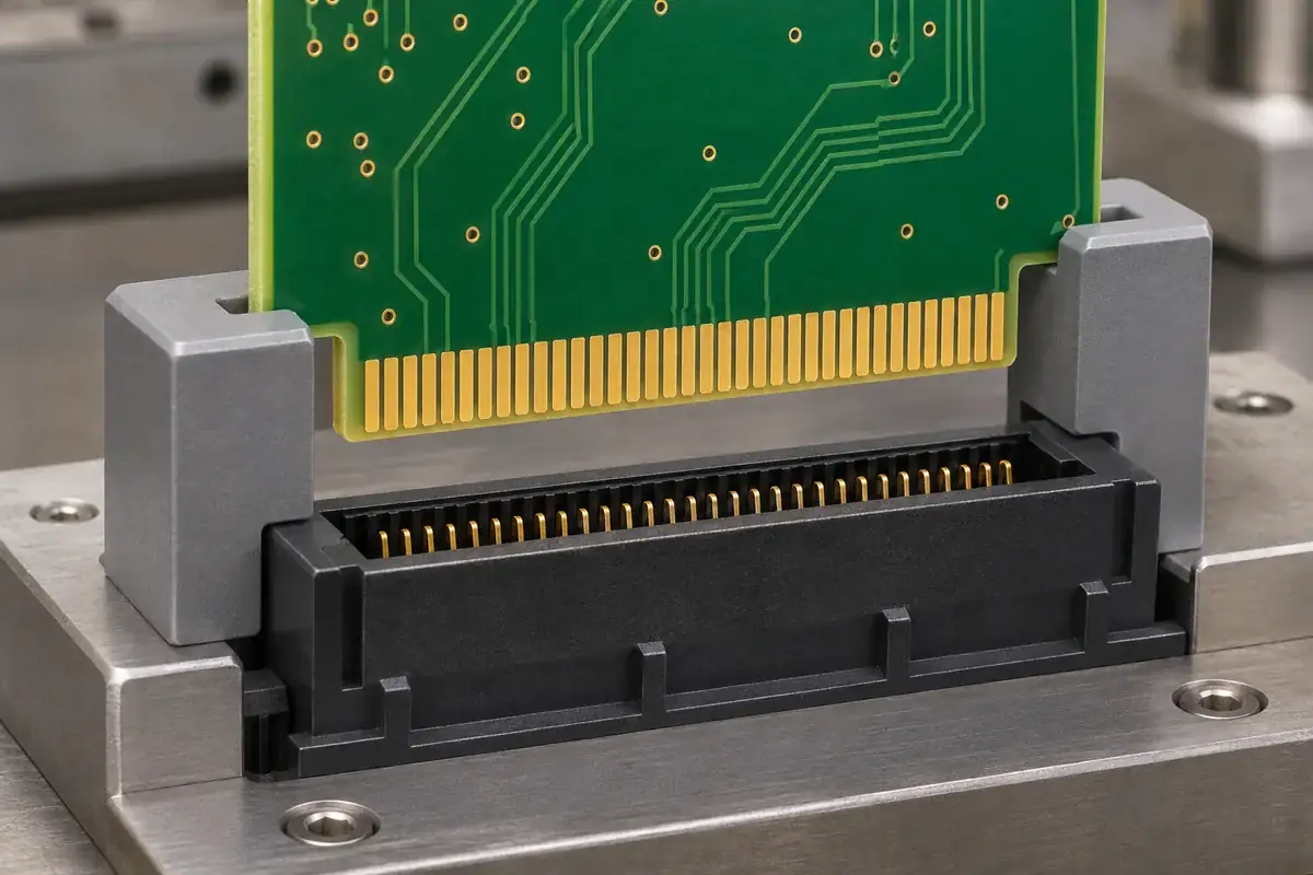
Avoid support features that fight the connector alignment
The connector and guide system must agree on the card's final position. If a guide fixes the board laterally while the connector has its own alignment feature, both mechanisms need to be considered together. A rigid guide that holds the board at the wrong location can defeat an alignment feature even when each component appears individually well made.
Samtec's MEC5 processing guidance discusses this interaction for its particular justification-beam arrangement. Apply that example as a prompt to identify the controlling feature in your own design. Do not assume every card-edge socket has the same compliance or should use the same guide geometry.
Distinguish the controlled directions. A support can resist out-of-plane movement while allowing a defined amount of movement in another direction, if the assembly design calls for it. That decision belongs in the mechanical interface definition. Unspecified looseness is not the same thing as a deliberately designed and evaluated accommodation of tolerance.
Consider the sequence of final fastening as well. Locating the board, engaging the connector and securing a remote bracket in different orders can produce different assembly states. Agree an order that corresponds to the intended references. If the order is essential to achieving the approved condition, include it in the assembly documentation.
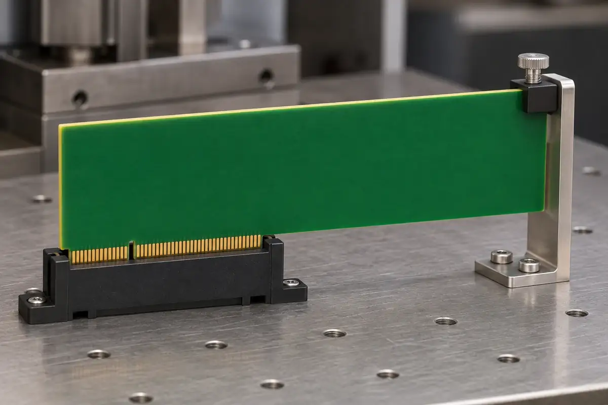
Make service removal part of the support review
A support arrangement must allow the intended removal path. Releasing a bracket may leave the board unsupported while the contacts are still engaged, and pulling from an accessible corner can introduce an unintended angle. The orientation and access guide examines how installed space changes those operations.
Use the actual card envelope when evaluating access, including components and attached items that affect handling. An empty board can demonstrate basic guidance but may be much easier to grip or maneuver than the assembled product. State which stage the sample represents so an early mechanical trial is not mistaken for a complete serviceability review.
For assemblies with multiple sockets, combine the support review with the multiple-connector alignment analysis. A long card can amplify conflicting locations across separate interfaces. Define the main references, any intended accommodation and the installed support condition before asking molding tolerances alone to solve the stack.
When requesting custom card-edge housings, provide the guide and bracket arrangement along with the connector and board drawings. Identify insertion, installed and removal loads that the plastic component must accommodate. This gives the tooling and sample plan a concrete mechanical context without assigning unsupported structural performance to a standalone housing.