
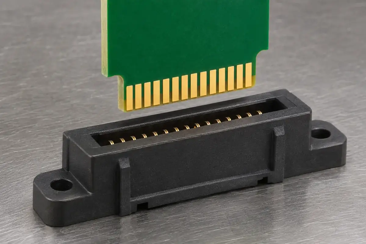
A board that enters a card-edge connector has passed one mechanical check. It has not necessarily established the intended contact condition. The plastic slot must admit and guide the finished board, while the metal contacts must operate over their specified deflection range. A loose fit in one region can coexist with excessive force in another, so pushing a sample into place is an incomplete acceptance method.
The useful starting point is the finished board definition, including the contact area, rather than a laminate catalogue thickness. Bring that definition together with the connector drawing and the molded-housing references. This makes it possible to separate a plastic clearance problem from a contact-system problem before adjusting a tool or asking the PCB supplier to change its process.
Product design illustrations accompany the interface and manufacturing explanations below.
Measure the thickness that the connector actually encounters
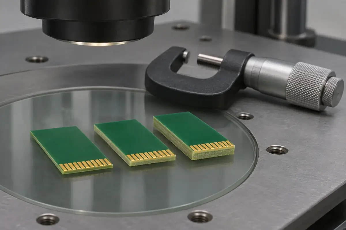
The board edge can contain laminate, copper and a specified contact finish. Other areas may include solder mask or different surface features. A thickness measured away from the mating edge may therefore describe a different stack from the one moving through the socket. Identify the location and surface condition relevant to each requirement instead of treating every board measurement as interchangeable.
Nominal thickness also needs a tolerance and a defined measurement method. A single prototype near the middle of its permitted range cannot represent every allowed production board. Review the board supplier's finished requirements, including local variation where it affects the mating interface, and consider how those conditions combine with the socket's permitted dimensions.
EDAC's 305 series information identifies the nominal board thickness accepted by that connector family. Its specific drawings remain the reference for the selected configuration. This is a useful example of why board thickness belongs in connector selection, without treating one manufacturer's nominal value as a universal requirement for custom molded housings.
A board with an edge bevel adds another distinction. The thin leading region starts the insertion, but the full finished thickness follows it. A coupon may enter the mouth easily and still encounter difficulty later. Record whether the observation concerns initial entry, travel through the slot or the final seated position; those observations point to different features.
Separate the molded guide space from the contact opening
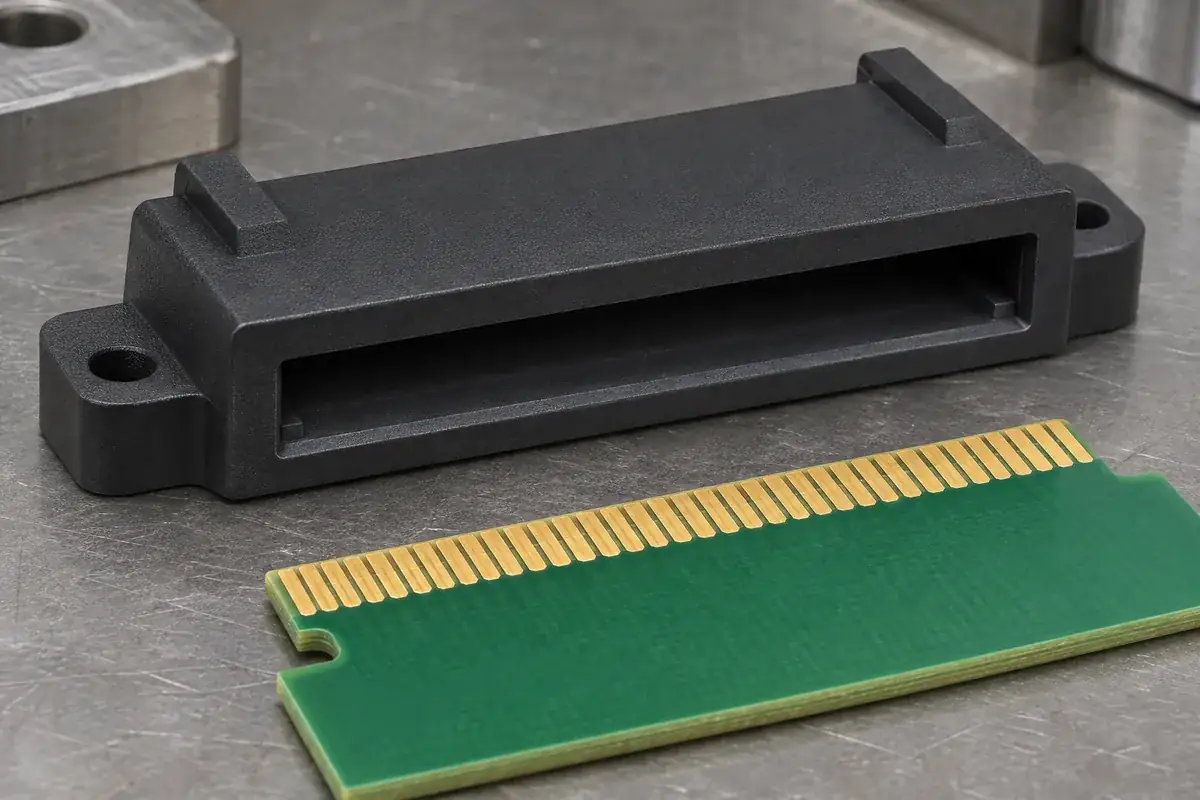
The visible slot is not always the narrowest part of the working interface. Entry lips, internal guide surfaces, a polarizing key and spring contacts can each establish a local restriction. Inspect the empty housing where practical, then compare it with the completed socket. This helps identify whether resistance originates in plastic geometry or in the installed contact arrangement.
Increasing slot width may remove a plastic rub while leaving the contact condition unchanged. It can also reduce the guidance that keeps the board centered during insertion. Before changing the molded feature, identify which surface is supposed to locate the board and which merely provides clearance. A clearance adjustment should not silently remove a locating function.
For the contacts, the relevant relationship includes the unloaded geometry, the board thickness and the contact's intended working travel. The housing supports and locates that system but does not independently establish its electrical performance. Obtain the contact or completed-connector requirements rather than deriving a permissible thickness from the appearance of the plastic opening.
The housing's molding condition matters as well. Local flash, an inward wall shift or distortion along a long slot can change clearance even when an overall dimension appears acceptable. Locate the measured sections where the board passes. If the part has multiple cavities, keep cavity identification in the sample review so an average does not hide a local manufacturing issue.
Evaluate the board in its installed references
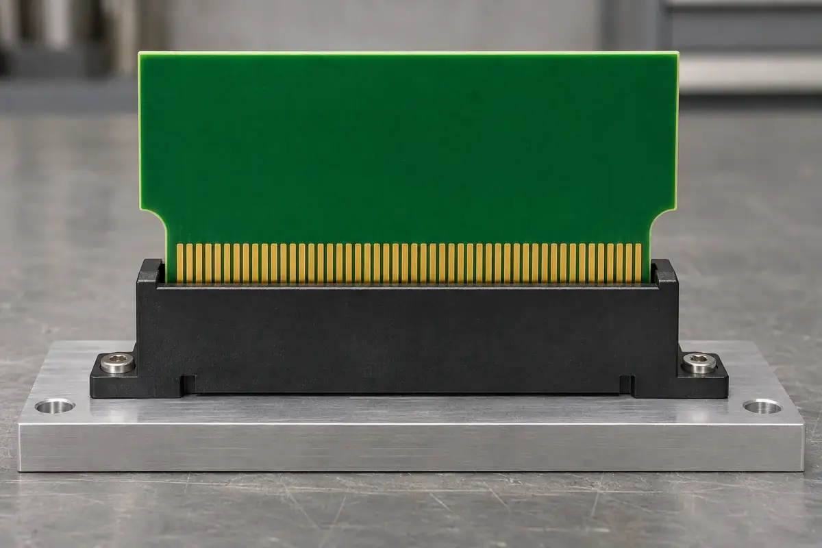
A board can fit an unmounted socket but bind once the connector and guides are fixed in a chassis. Mounting can constrain the housing, and a guide can direct the board toward a different center plane. Include the actual mounting arrangement in the investigation. Otherwise a housing modification may compensate for a fixture conflict that returns in the finished equipment.
Board bow or twist creates a related problem. The thickness at a local section may be acceptable while the card approaches the slot at an angle along its length. Forcing the board straight through the contact system is not a substitute for agreeing the permitted board shape and support condition. Examine the approach before interpreting a high insertion force as a thickness failure.
Use identified samples that represent the dimensional conditions being reviewed. A thin and a thick coupon can help explore the interface, but each needs the relevant finish, bevel and outline. A plain plastic strip of similar nominal thickness may help check a simple clearance, yet it does not represent the contact-facing surfaces or the behavior of the actual PCB.
For each configuration, document the board revision, connector revision, support arrangement and observation point. Separate entry effort, full insertion and removal rather than reporting that a board feels tight. If force measurements are required, agree the fixture, direction, speed and acceptance limits with the responsible connector engineer before using those results for approval.
Turn the findings into a controlled housing requirement
A useful drawing links the slot profile to the mounting and contact references. State where width is inspected and which local features must remain clear of the board envelope. Our discussion of connector inspection datums explains why measuring a feature without its functional reference can give a reassuring result that does not describe assembly.
Agree the sample sequence before cutting steel. Empty-housing inspection can isolate molded geometry; contact installation checks add the terminal relationship; an installed board review adds the mating and support conditions. Keeping these stages separate helps identify the cause of a failed fit without confusing a promising first sample with a completed connector qualification.
The related guide to board bevels and housing entries covers the transition into the slot. Combine that entry review with the full-thickness condition here. A wider mouth cannot resolve every internal interference, just as a deeper bevel cannot justify an unsuitable final contact deflection.
For custom card-edge connector housings, provide the finished board drawing, contact definition and mounting arrangement together. Identify which interface is already approved and which still needs evaluation. That allows the molding proposal to address the actual plastic geometry, sample quantities and inspection evidence needed for the next decision.