
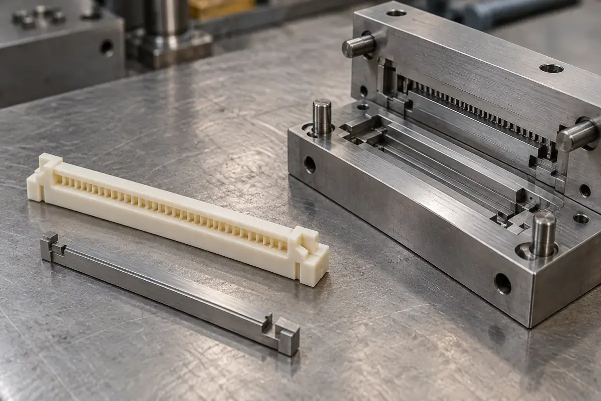
A long narrow cable slot looks simple in a plastic-part model: two walls separated by a small opening. In the mold, that opening needs steel with a defined support and removal direction. The surrounding plastic must release without damaging its guide edges or distorting the housing. Thinking about the empty space as a physical tool feature changes the design conversation.
The useful question is not whether a slot is generally moldable. It is whether the proposed core, parting arrangement, draft and ejection method can produce the required interface in the chosen material. A release-friendly change that moves the cable reference may solve the tooling problem while creating an assembly problem, so both sides need to remain visible.
Product design illustrations accompany the molded-component engineering explanations below.
Review the steel that occupies the slot
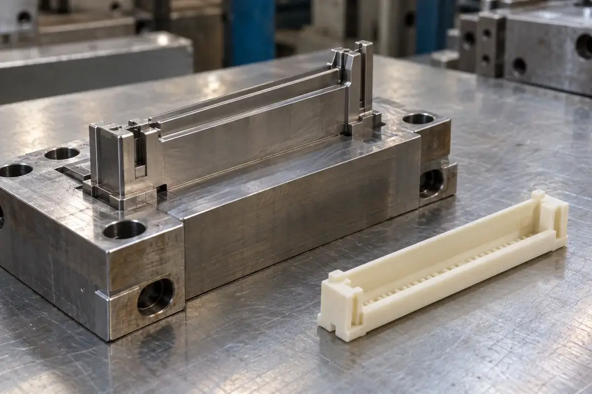
A slender core feature needs sufficient support around its working geometry. Unsupported length, local thickness and the way it joins the backing structure influence how it responds during molding and handling. The steel geometry also needs machining and finishing access. A perfect-looking plastic opening is not a complete tooling definition.
A separately replaceable insert may improve access and maintenance, but it introduces locating and shutoff interfaces. Those interfaces have to reproduce the slot position and prevent unwanted plastic from forming where the tool pieces meet. Splitting the tool can therefore make manufacturing easier while creating another relationship to inspect and maintain.
Where the plastic shape creates an undercut, the release direction may need a different tool action or an approved geometry change. The Protolabs discussion of side-actions describes how moving tool elements can release features that obstruct a straight pull. The appropriate arrangement remains dependent on the actual part.
Our connector mold-insert scope addresses the steel component that forms such geometry. That tooling component is separate from the delivered plastic housing. Its dimensional acceptance and the molded slot's acceptance should be connected through the design but recorded as checks on different physical items.
Place draft where the interface can accommodate it
Draft changes the separation between opposing surfaces along the removal direction. In a cable slot, that can also change the entry clearance, guide length or local support. The drawing should identify the functional section and reference position so that adding draft does not leave the nominal dimension attached to an unspecified point.
A generous entrance can help cable insertion, but it does not automatically permit the entire slot to taper in the same way. A short lead-in and a controlled guide region may serve different purposes. Keep these features distinct in the model so tooling and assembly teams can evaluate a change without interpreting one continuous surface differently.
Surface finish interacts with release. A texture or machining transition on a long wall can increase resistance locally, while polishing can alter a sensitive edge if not controlled. Specify the finish where it supports release and function, then preserve the dimensional references during finishing. A broad instruction to polish everything can create new variation.
Material shrinkage also affects the way plastic bears against the core as it cools. The relevant behavior depends on the selected grade, flow and geometry. It cannot be resolved by copying a generic draft value from a design guide. The review should use the guide to frame the problem, then assess the actual housing and process.
Make ejection support the housing rather than bend it
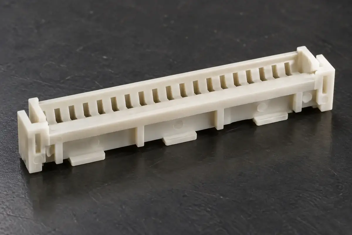
A long housing can be vulnerable if release force is applied only at a few poorly supported locations. Local pushing may flex a wall or leave a witness near a functional surface. The ejection arrangement should transfer force through regions that can carry it, with the direction and distribution considered alongside the way the part holds the core.
Protolabs' ejector-pin guidance connects pin placement with draft, texture and feature depth. This reinforces a practical principle: ejection is part of the part-design review, not a location decision made after every plastic surface has been frozen.
An ejector witness may be acceptable on a nonfunctional land while being unacceptable on a cable support or assembly datum. Mark permitted locations and conditions explicitly. Moving a pin away from a cosmetic face can increase bending elsewhere, so the preferred compromise should be based on the complete load path rather than appearance alone.
Thin guide walls can also be distorted by handling after release. If samples are stacked or pressed into a tray while still susceptible to shape change, the observed bow may not describe the cavity geometry alone. Preserve sample identity and handling conditions during development so tool, process and downstream effects can be distinguished.
Inspect the slot in a state that exposes release effects
A housing clamped flat can hide bow caused by release or cooling. Inspect the free state where it is relevant, then evaluate the defined mounted state separately. The distinction matters because a board or fixture may constrain the part in service, but it should not silently correct an incoming part during a dimensional check.
Review the slot along its length rather than at one convenient location. Local narrowing, edge damage or twist can interfere with a cable even when the average opening is acceptable. The method should relate those observations to the intended cable path. A detailed profile may be more informative than several unrelated point dimensions.
The cosmetic and functional inspection article explains why a drag mark needs context. A harmless surface witness and a raised edge that touches the cable can look similar in a photograph. Describe the location and physical effect before deciding whether a tool finish change, process change or acceptance clarification is needed.
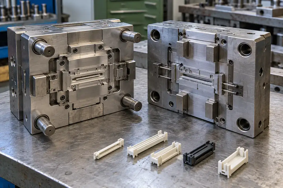
For custom FPC and FFC housings, provide the cable-interface definition with the plastic model so release proposals can be reviewed against function. The molding development scope should connect core support, draft, ejection and sample inspection. The aim is a housing that leaves the mold intact and retains the interface it was designed to provide.