
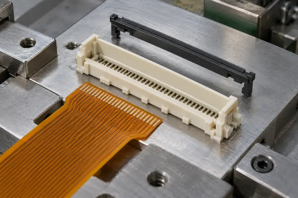
A cable that appears straight at the connector mouth may still be short of its intended seat. The actuator may even move toward its closed position without revealing the error immediately. Insertion depth is therefore more than the distance from the visible housing edge to the cable end. It is a relationship between the cable, its stop features and the working region inside the connector.
The molding review should begin by identifying what is supposed to stop the cable. A rear wall, local abutments, cable ears or another feature may establish the final position. The chosen design determines the answer. An unrelated internal obstruction that happens to stop insertion is not an acceptable substitute for the intended seating reference.
Product design illustrations accompany the molded-component engineering explanations below.
Trace the seating chain from the cable end
The leading edge establishes one possible reference, but the conductive pads are located relative to that edge through the cable design. A housing can stop the cable consistently and still place those pads incorrectly if the cable definition is incompatible. Review the pad region, leading edge and any reinforcement boundary together rather than approving the housing stop in isolation.
The cable width and edge condition affect how it reaches the stop. If one corner catches a guide, the opposite side may advance farther and create a skewed seat. A central view can conceal this condition. The assembly definition should identify how seating is confirmed across the relevant width and how much angular freedom the guides permit.
For an illustrative straight-entry design, two separated rear abutments can reveal end-to-end seating more clearly than one central point. They can also create a sensitivity to cable-edge squareness and local molding variation. A continuous rear wall may distribute support differently but can be harder to inspect. The selection depends on cable geometry and the mechanism's working needs.
Hirose's FH26 instructions call for full insertion before actuator closure and describe recovery from misalignment. That sequence supports a useful distinction: closing the actuator and establishing the cable's intended seat are separate actions.
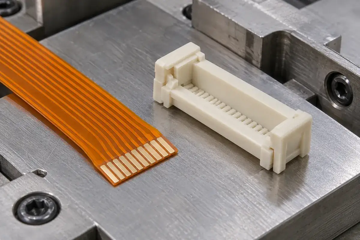
Distinguish a true stop from premature resistance
A stiffener step can meet the housing entrance before the cable end reaches the rear stop. Flash or a displaced internal feature can create a similar sensation. More pushing force is not a diagnostic method: it may bend the cable or load delicate connector features. Identify the actual contact location before changing either the housing or the assembly method.
The actuator's open state also matters. If it has not reached its specified insertion position, the cable can encounter a mechanism that should have been clear. The required open position and insertion direction are product-specific. Some connector designs use different paths, so a generic instruction to push horizontally should not replace the selected assembly guidance.
The cable-thickness article explains why the local stack can alter entry and closure. Here, that stack is part of the seating chain: a cable whose construction does not match the intended interface may never reach the correct stop even when its outline and conductor pitch appear suitable.
During development, inspect both the intended stop and any surfaces that could touch first. A sectioned model or an accessible prototype can help establish the sequence. Treat such observations as design evidence for the identified configuration. They do not establish a universal insertion depth or allowable force for all FPC and FFC connectors.
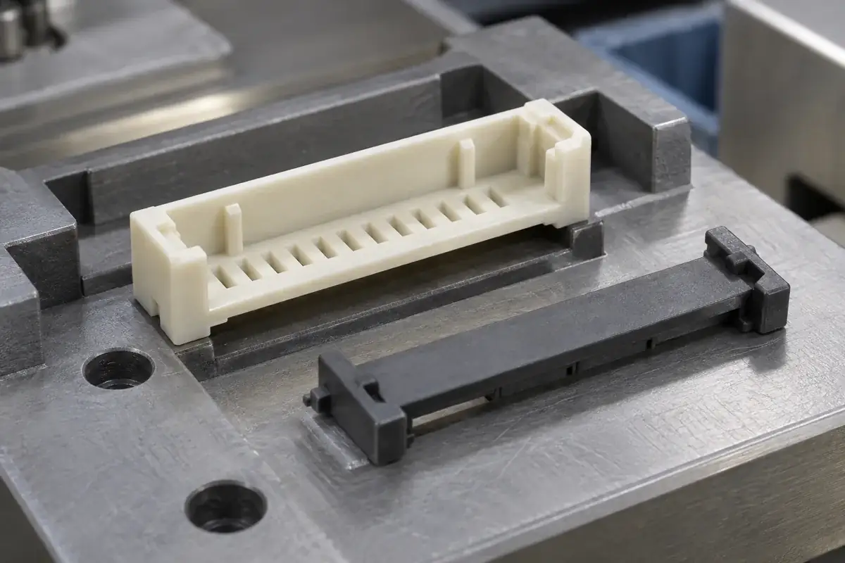
Make the stop inspectable without changing its function
A stop hidden deep inside a long slot may be difficult to measure from the exterior. The drawing needs a datum scheme and a measurement method that represent the actual seating relationship. Referencing the stop from a convenient outer wall can be misleading if that wall is not controlled relative to the contacts or mounting interface.
Optical access, part orientation and lighting affect what can be inspected reliably. A sharp shadow can be mistaken for the end of a recess, while contact probing may distort a thin housing. Review the method early enough to influence the design. A dimension that cannot be checked consistently will create disagreement even if the nominal geometry is clear.
Adding a viewing opening can make seating visible, but it removes material and may alter local stiffness or molding flow. It can also reveal only one part of the cable edge. A visual indicator should therefore be connected to a functional reference and evaluated for false indications. Visibility is helpful when it corresponds to the condition the assembly actually needs.
The stop edge condition matters as much as its nominal position. A local burr or flash can shift the first contact point, while excessive rounding can change how a flexible edge settles. Specify the surface and edge requirements where they affect seating. Applying an extreme cosmetic finish to unrelated exterior walls will not control this functional contact.
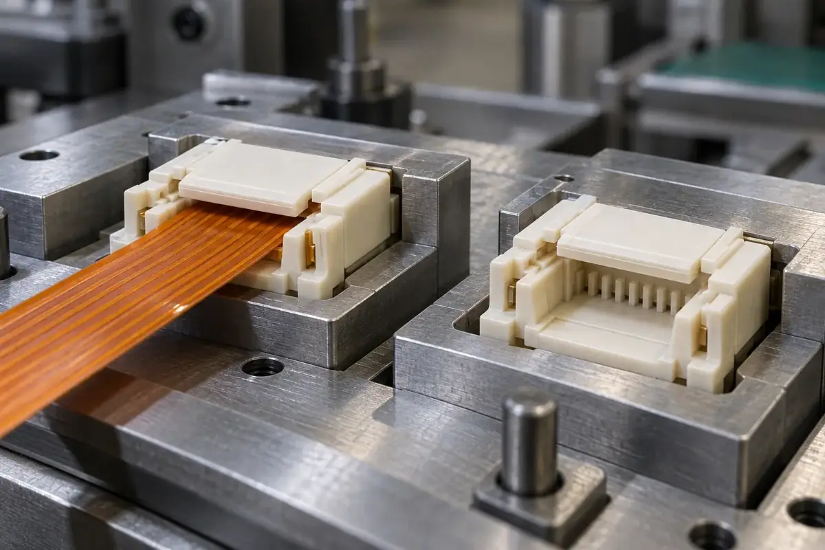
Connect seating confirmation to closure and retention
Once the cable is seated, operating the actuator should preserve the intended position. A mechanism that drags the cable during closure can turn an initially correct seat into an incorrect final condition. Evaluate the sequence with the intended support and cable route, particularly if an external bend applies a restoring load near the connector.
Retention and insertion depth are related but distinct. A cable may resist withdrawal while its pads remain short of the intended working region. Conversely, a correctly seated cable may require the actuator to reach a defined engagement state before retention is established. The latch-engagement review keeps these conditions separate in the acceptance plan.
For molded-part approval, identify stop location, guide condition and permitted edge evidence. For assembly approval, identify cable revision, operating sequence and the required seating indication. Electrical verification belongs to the complete specified assembly. This division makes it possible to trace a failed check back to the relevant component or operation without making unsupported conclusions from appearance.
FECISION's custom connector housing and actuator scope can review these molded interfaces alongside the counterpart drawings. The same reference discipline applies to other connector insulating bodies. A well-defined stop creates a repeatable seating condition because the whole path has been considered, not simply because a rear wall is present.