
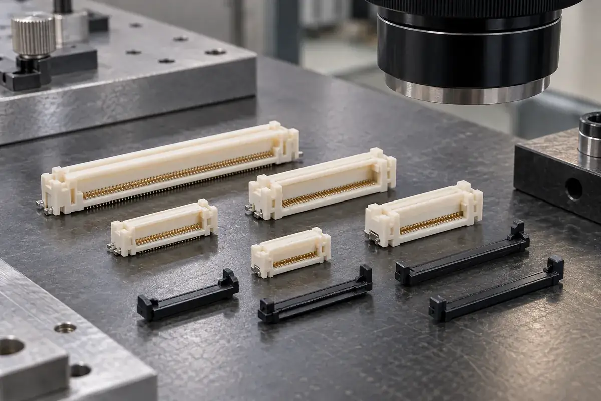
A faint line on the outside of an FPC housing may be harmless, while a much smaller raised edge inside the cable mouth can prevent correct seating. Calling both conditions a cosmetic defect loses the distinction that matters. Inspection should classify an observation by its location, physical form and effect on the intended interface before assigning an acceptance decision.
This is especially important for small molded components because visual size can be misleading. A feature that occupies little of the overall part may consume a meaningful share of a local clearance. Conversely, a visible surface witness on a nonfunctional region can attract attention without affecting assembly. A useful plan directs inspection effort toward the relationships the part controls.
Product design illustrations accompany the molded-component engineering explanations below.
Divide the part by function before judging appearance
Map the cable entrance, guide surfaces, stops, pivot seats, latch shoulders and assembly datums. Then identify exterior areas whose appearance matters for handling or the finished product. The categories may overlap, but they should not be assumed identical. A functional surface can need a specific edge condition without requiring the same appearance standard as a visible exterior face.
Describe a mark physically. Is it a color change, a depression, a raised projection, a crack or missing material? A photograph may show contrast without establishing height or depth. Where the effect depends on geometry, follow the visual observation with an appropriate dimensional or surface check rather than deciding from darkness or brightness alone.
Flash near a cable path is different from a permitted parting-line witness away from contact. The first can alter the effective opening or produce debris; the second may simply indicate how the tool divides. A blanket zero-mark requirement can be difficult to interpret while still failing to identify the critical area. Location-specific criteria are more actionable.
The long-slot mold-release article connects these observations to core support and ejection. A drag witness, raised edge and distorted wall can have different origins. Recording the condition precisely helps determine whether the response belongs in tooling, molding, handling or the acceptance definition.
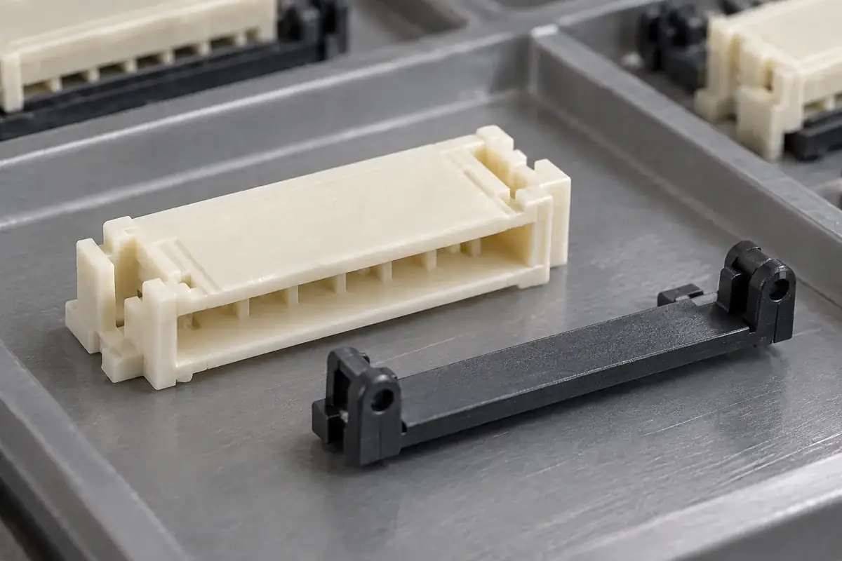
Choose a measurement state that represents the question
A free housing may bow while appearing straight when pressed into a fixture. Neither observation should be hidden: the relevant acceptance state depends on the drawing and assembly requirements. State whether dimensions are checked free, lightly located or constrained in a defined way. Without this information, different inspectors can produce valid measurements of different physical states.
Long slots need a view that reveals variation along their width. A single measurement near an accessible end can miss a central restriction. The same principle applies to an actuator whose ends establish the working position while its middle is flexible. Select locations or a profile method based on function rather than measurement convenience alone.
Contact pressure can influence thin features. A probe or gauge may spread walls, bend a latch arm or flatten the part against a support. Optical inspection avoids some of these forces but introduces its own requirements for focus, lighting and interpretation. The chosen method should be evaluated for the feature and the decision it is expected to support.
Visual conditions should also be controlled. Magnification, lighting direction and background can change the apparent severity of a mark. Reference samples are useful when they identify the feature, viewing condition and acceptance meaning. An unlabeled photograph of a good-looking part is a weak standard because it does not explain which differences matter.
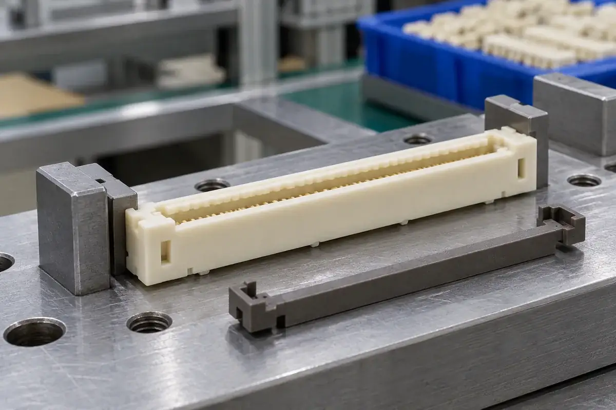
Keep functional checks tied to identified assemblies
A cable insertion check can reveal interference, but it depends on the cable construction, orientation and seating method. A check using an unrecorded cable is difficult to interpret when a later sample behaves differently. Keep the counterpart revision and condition with the result. The cable-fit discussion explains why nominal pitch is not enough.
Actuator operation should likewise use the intended support and sequence. If one inspector presses the center and another loads the ends, they may produce different results without either part changing. The method should follow the selected mechanism and assembly definition. An unexplained tightness observation is a reason to investigate, not a complete acceptance criterion.
TE's FPC connector overview presents different contact arrangements and insertion concepts. Those distinctions reinforce the need to identify the tested configuration before interpreting a functional check or comparing it with another connector.
Electrical checks belong to the complete specified connector assembly. The appearance of an empty plastic housing does not establish current rating, contact resistance or signal performance. Similarly, successful cable retention in one trial does not establish durability over an unspecified duty. Name the evaluated item and test condition so the result remains useful without being expanded beyond its evidence.
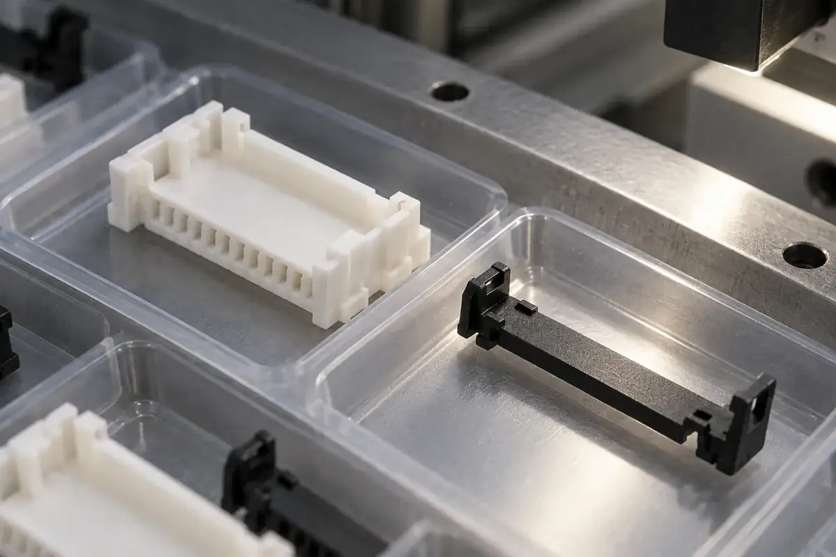
Turn inspection findings into a controlled correction
When a defect is found, preserve the sample and its traceability before repeated assembly changes its condition. Record the cavity and revision where available, the observed location and the method used. This makes it possible to compare the molding, tooling and assembly evidence rather than relying on a verbal description after the feature has been damaged further.
Look for patterns without inventing a cause. A condition confined to one cavity suggests a different investigation from one shared by every cavity after a material change. A mark appearing only after packaging points elsewhere again. These patterns guide the next check, but they are not proof until the relevant mechanism has been examined.
After a correction, repeat the check that exposed the problem and any connected checks that the change could affect. Removing a raised edge may alter a guide dimension; changing ejection can influence free-state shape; rounding a latch can change retention. Verification should follow the consequences of the correction rather than merely confirm that the original photograph looks cleaner.
FECISION's custom housing and actuator review connects these inspection requirements to the molded drawing. The broader connector insulator scope uses the same evidence boundary. Good inspection distinguishes acceptable manufacturing evidence from conditions that alter function, then records a decision that another team can reproduce.